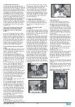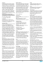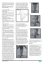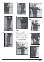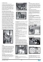
-4-
www.igmtools.com
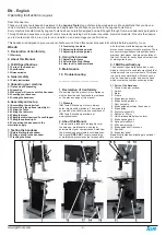
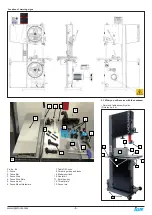
The bandsaw does not have many parts. The
major parts are discussed in this manual. If you
are not familiar with the bandsaw, take the time
to read this section and become familiar with
the machine.
1. Tension indicator/window
Tension indicators are designed to indicate
the compression of a spring. As a rule, the
greater the spring compression, the greater
the tension on the blade. The tension scale
does not register until the blade is relatively
taut and is located on the inside of the body of
the bandsaw. The tension scale is a general
reference and not a rule. It is visible with the
upper door closed by looking through the
tension indicator window.
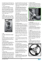
2. Switch
To start the machine press the “I” button on
the start stop switch. To shut off the machine
press the “O” on the start stop switch. When
the safety switch is pressed it stops the power
to the motor. To reset it, twist and it will pop out
and allow power to be supplied to the motor.
.
3. Motor
The bandsaw is supplied with a 2,2kW, 400V
motor. It drives the lower flywheel through a
drive belt.
4. Frame
The frame of the bandsaw is a U-shaped frame,
which houses all the parts of the machine.
This is the heart of the bandsaw and has to be
very rigid, as it takes the strain of the blade
being tensioned.
5. Blade tension handle
The blade tension handle moves the blade
tension and tilt assembly vertically. The vertical
action compresses a spring that ensures
that the blade tension is constant and will
not change dramatically as the blade length
increases due to the heat generated by the
cutting action.
6. Blade tracking window
There is a blade tracking window on the side
of the frame that allows the edge of the upper
flywheel to be viewed. This allows the tracking
of the blade to be achieved with the door
closed.
7. Cast iron table
The table supports the work piece and can tilt
(-6 degrees to +45 degrees) to produce cuts at
various angles. It has a groove to the right-hand
side of the blade, which is used to guide the
miter gauge. In the center there is a table insert
which the blade passes through. Should the
blade wander off center, this table insert will
protect the blade from damage, as it is soft and
should not damage the blade. The table also
supports the adjustable fence, which is used for
parallel cuts. There is a nut and bolt that joins
both sides of the table and stops the table from
warping. The nut and bolt must always be fitted
in the table and only removed when removing
or fitting a blade.
8. Blade guide adjustment hand wheel
The upper blade guides are attached to the
blade guide shaft. The shaft is vertically
adjustable with a hand wheel. The guides
should be adjusted so the guides are just
above the wood being cut. This gives the blade
maximum stability and is also the safest way to
operate the bandsaw.
9. Blade guides
There are two sets of blade guides, one above
and one below the table. The function of the
guides is to give the blade stability and ensure
that the blade movement left/right, forward/
back is kept to a minimum. The guides above
the table are fitted to a shaft that has vertical
adjustment. The upper guides are adjustable so
that the guides are held just above the job being
cut. This gives the blade the maximum amount
of stability and also keeps the amount of blade
that is exposed to a minimum. The guides have
ceramic inserts that can be adjusted for almost
zero clearance.
10. Rip fence assembly
The rip fence assembly consists of a guide rail,
cast knuckle, fence attachment casting, rule
and a high-low fence. The guide rail is attached
to the table side. It guides the fence assembly
across the table. The cast knuckle slides on the
guide rail and is lockable in any position to
suit the width of cut. The fence attachment
casting is attached to the cast knuckle with
three screws that when loosened allow the
fence to be adjusted for drift. The fence is
attached to the fence attachment casting with
two studded knobs that allow the fence to be
adjusted laterally across the table to suit the
job being cut. The fence can be fitted in the low
position or the vertical (7 1/4“ height) position.
There is a rule that is fitted to the side of the
table and can be used as a quick guide on the
distance that th
The Fence Stop can be used for non through
cuts and can be set on any length of the fence
with the quick release handle.”e fence is from
the blade.
Note
. The rule will have to be adjusted each
time the fence is adjusted for drift, as this will
change the distance the fence is from the blade.
11. Dust ports 100 mm
The bandsaw produces a lot of sawdust, so
extraction is very important. This is achieved by
connecting a 100mm dust extraction hoses with
a minimum capacity of 1699 m
3
/h to the two
dust ports located at the back of the machine.
The stronger the suction from the dust collector,
the better for you and the machine.
12. Quick-release blade tension lever
There is a quick-release tension lever at the
back of the bandsaw. The lever is a convenient
way of quickly releasing the tension on
the blade and speeds up blade change
dramatically.
13. Blade-tracking knob
The blade-tracking knob is located at the back
of the bandsaw and is used to adjust the blade
tracking. The knob must be locked once the
adjustment is completed.
14. Optional mobility kit
The optional mobility kit is fitted to the base of
the bandsaw and consists of two fixed wheels
at the front of the bandsaw and a swivel wheel
at the back of the band saw. The swivel wheel
is activated and deactivated with a foot lever.
With the swivel wheel deactivated, the bandsaw
sits on two rubber feet.
15. Optional light
The optional light is fitted with four screws
through pre-drilled holes at the top of the
bandsaw. The bandsaw is provided with a 220V
socket that the light can be connected to.
16. Blade guide shaft lock
The upper blade guide is fixed to the blade
guide shaft, which is vertically adjustable. Once
the guides have been adjusted vertically, the
shaft is locked in position with the lock knob.
17. Flywheel
The blade is suspended over two wheels that
are covered with rubber called a „tire“. The tire
cushions the blade and protects the teeth from
coming in contact with the metal of the flywheel.
The lower wheel is the drive wheel and is
attached to the motor with a rubber drive belt.
The lower flywheel powers the blade and pulls
the blade down through the work piece. The
top wheel has two functions. One function is to
balance or track the blade on the wheels, and
the second one is to tension the blade. Both
functions are adjustable.
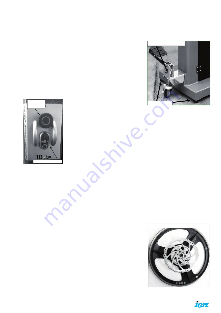
18. Brake
The bandsaw is provided with a brake that is
operated by applying the foot pedal. When the
foot pedal is applied, the power is removed
from the motor and the flywheel is slowed by
the disc break.
Rubber feet
Swivel wheel assembly
Disc break on flywheel
Emergency
stop button
Start / Stop buttons


