


31
C
ONVEYOR
M
OUNTING
B
OLT
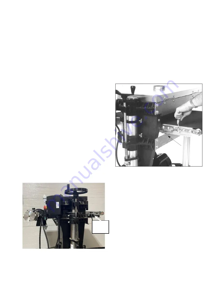
REPLACING CONVEYOR BELT
To replace the conveyor belt, the conveyor assem-
bly must be removed from the machine. Lower the
conveyor table to its lowest position with the
height adjustment handle. Remove the bottom
cover from control box, rotate shaft to access set
screws in shaft coupler.
Important: Disconnect
power to sander!
Loosen two set screws from
shaft coupler, (@90º). Remove the four bolts
holding the conveyor motor control box base
bracket (Fig. 29). Remove conveyor motor
control box and place on dust cover or separate
stand. Loosen the conveyor take-up screws (Fig.
27 and Fig. 28) to relieve belt tension and slide the
driven roller fully inward. Remove the four bolts
that attach the conveyor assembly to the table
mount brackets (see Fig. 28). Lift the conveyor
and remove it from the machine by sliding the
conveyor out, toward the front of the machine.
Avoid tearing the belt on any edges underneath
the conveyor bed during removal. Reverse the
procedure for re-installation.
Note
: If the conveyor belt continually tracks to
one side of the machine, first try reversing the belt
on the conveyor bed. If this doesn’t remedy the
problem, place a level on the conveyor bed to
make sure the conveyor bed is not twisted. If
squaring up the bed does not remedy the
problem, proceed with the
following steps:
Fig. 27. Conveyor belt replacement
Step 1. Check the conveyor drive and driven roller
to make sure they are parallel to the surface of the
conveyor bed. To do this, first center the conveyor
belt on the bed. Then lay a straight-edge on the
exposed edge of the conveyor table on the left (out-
board) side, extending it over the drive roller, then
driven roller. Note the distance between the drive
roller then driven roller and the straight-edge.
Fig. 28. Tensioning and tracking conveyor belt.
Step 2. Now repeat Step 1 on the right (inboard)
side of the conveyor. Compare the measurements
from side to side. If they are not equal, loosen one of
the brackets that hold the drive or driven roller in
place. Tip this bracket until the distance between the
drive or driven roller and the straight- edge are equal
from side to side, then tighten the bracket.
Tracking
Nut &
Wrench
Summary of Contents for 37x2
Page 36: ...36 SUPERMAX STAND ASSEMBLY...
Page 39: ...39 SUPERMAX DUAL DRUM HEAD ASSEMBLY...
Page 43: ...43 CONVEYOR MOTOR...
Page 45: ...45...
Page 46: ...46 NOTES...


