31
PX|22 Sheartec:II Planer \ Maintenance
Adjustment of Pressure Bar
WARNING
·
TURN PLANER OFF AND DISCONNECT POWER BEFORE PERFORMING ANY MAINTENANCE OR ADJUSTMENTS!
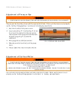
The pressure bar should be set even with the lowest point of knife. Make sure the knives are set properly
see the “Setting / Changing Knives” section prior to making any adjustments.
1. Disconnect machine from power source.
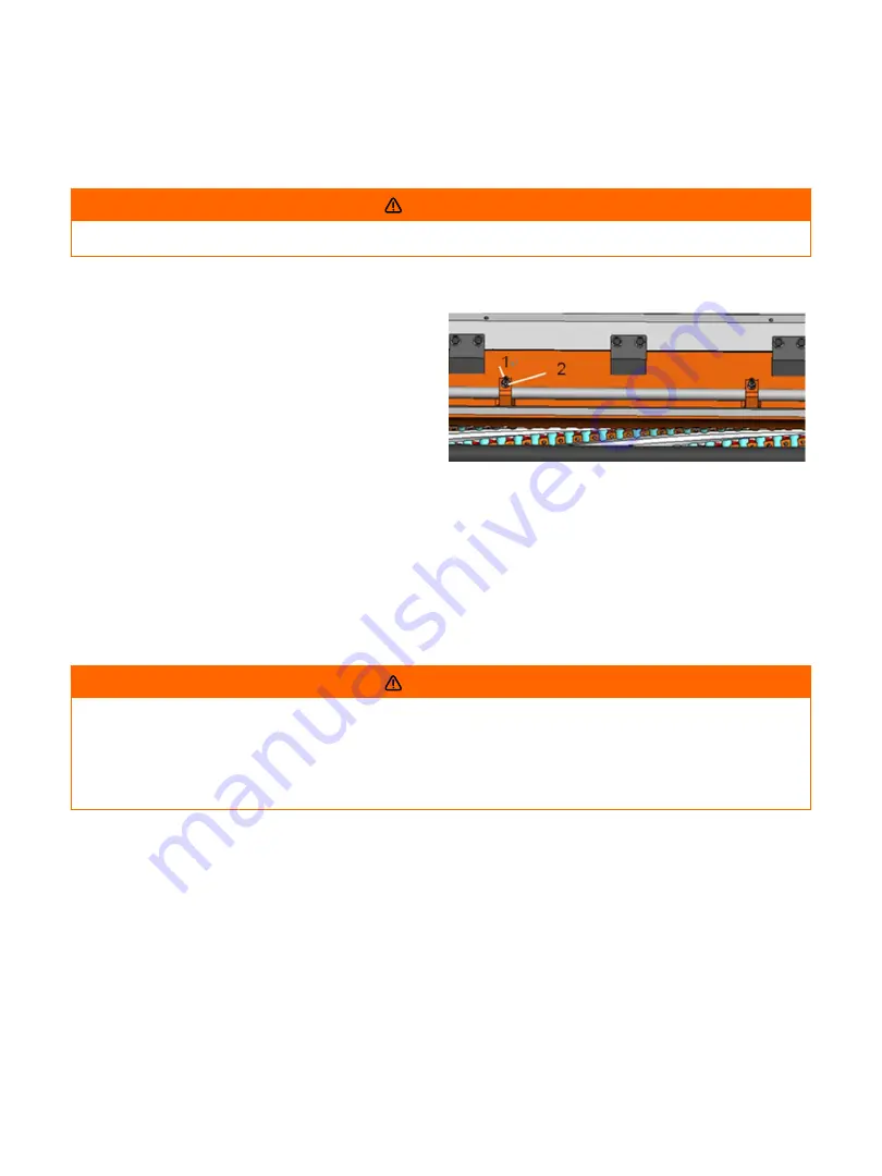
2. Loosen screw (Fig. 19, 1) and nut (Fig.19, 2) turn
the screw to the right so that the pressure bar
moves upward. Place gauge block and 0.2m/m
thickness gauge (Fig.17, A) under the
cutterhead.
3. Place gauge block under pressure bar.
4. Make pressure bar touch the top of the gauge
block.
5. Finally, tighten the screw and replace the nut.
FIG. 19: PRESSURE BAR ADJUSTMENT
Adjustment of Out-feed Roller
WARNING
·
TURN PLANER OFF AND DISCONNECT POWER BEFORE PERFORMING ANY MAINTENANCE OR ADJUSTMENTS!
·
MAKE SURE ALL KNIFE INSERT SCREWS ARE TIGHTENED SECURELY. LOOSE INSERTS CAN BE PROPELLED AT HIGH
SPEED FROM A ROTATING CUTTERHEAD, CAUSING INJURY.
·
TORQUE EACH SCREW TO 52-60 IN/LBS.
·
KNIVES ARE EXTREMELY SHARP. BE VERY CAREFUL WHEN HANDLING KNIVES. FAILURE TO COMPLY MAY CAUSE
SERIOUS INJURY
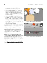
The out-feed roller should be set 0.02” below the lowest point of knife. Make sure the knives are set
properly see the “Setting / Changing Knives” section prior to making any adjustments.
Summary of Contents for MPLANPX2210-0130
Page 1: ...PX 22 Sheartec II Planer Owner s Manual MPLANPX2275 0130 MPLANPX2210 0130 3 10 2021...
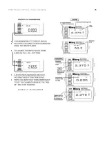
Page 25: ...25 PX 22 Sheartec II Planer Setup Assembling FIGURES 10 12 DRO ADJUSTMENT...
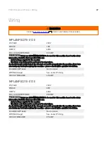
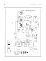
Page 38: ...38 PX 22 Sheartec II Planer Wiring...
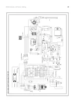
Page 39: ...39 PX 22 Sheartec II Planer Wiring...
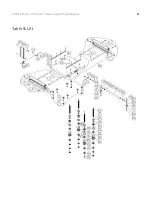
Page 41: ...41 PX 22 Sheartec II Planer Replacement Parts Diagram Table Lift...
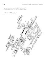
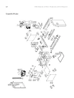
Page 42: ...42 PX 22 Sheartec II Planer Replacement Parts Diagram Stand Motor...

