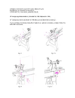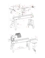
1, With an assistant, attach the extension bed to lathe bed right end with two head cap
bolts B. Slightly tighten the bolts. These two bolts must be taken off as soon as swing
away system assembly is completed (Fig.9)
2, Adjust the extension bed flush to the lathe bed. Make sure inside ways and surfaces are
aligned.
3, Slide the tailstock back to the position as show in figure. X=30mm or 1-
1/2” (Fig. 10)
4, Rotate the lock handle until the tailstock locked firmly. Now the extension bed is well
aligned with lathe bed (Fig. 11)
5, Put the two eccentric pivot pins in lathe bed, turn the pins until it slightly touch extension
bed bottom. Secure pivot pins with nuts D (Fig.9)
6, Mount the hinge between lathe bed and extension bed with head cap screws, spring
washers and flat washer (Fig.11).
Do not
tighten head cap screws at this moment. Use
alan wrench to tun the set screws until it hit beds. Then firmly tighten bolts.
7.,Mount clamping device on both lathe and extension bed as shown on Fig.12.
Operation of Lathe
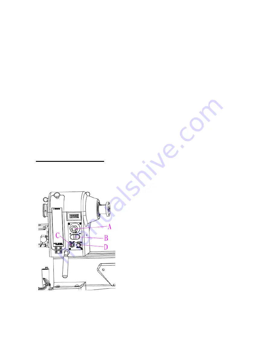
Control Panel Information (Fig. 13)
Fig. 13
A, Spindle speed readout: Indicates the
spindle speed in RPM.
B, On/Off Switch: Turns lathe ON and OFF
NOTE:
If a sudden power failure occurs,
the spindle will not re-start automatically
when the power is restored to the machine.
Push the off button
C
to reset the switch,
and then press the on button
D
to restart
the lathe.
C, Spindle direction switch: Toggles the
spindle direction between forward or
reverse.
Forward: Spindle rotates towards you;
Reverse: Spindle rotates away from you;
D, Speed control knob: Adjust the spindle
speed within the range.


