background image

21

PXl16 Sheartec:II Planer \ Setup  Assembling

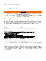
Power Supply Circuit Requirements 

The power source circuit for your machine must be grounded and rated for the amperage given below.
Never replace a circuit breaker on an existing circuit with one of higher amperage without consulting a
qualified electrician to ensure compliance with wiring codes. If you are unsure about the wiring codes in
your area or you plan to connect your machine to a shared circuit, consult a qualified electrician.

Circuit Size (208-230V, Single Phase) ........30 Amp (minimum)

 DANGER!

IN ALL CASES, MAKE CERTAIN THE RECEPTACLE IN QUESTION IS PROPERLY GROUNDED. IF YOU ARE NOT SURE,

HAVE A QUALIFIED ELECTRICIAN CHECK THE RECEPTACLE.

Motor Specifications

The typical main motor is 5 HP and is typically wired for 220 Volt, Single Phase, 60 HZ, AC current. Confirm
your motor electrical configuration before connecting power! Before connecting the machine to the power
source, make sure the starter and switches are in the "OFF" position. Cord and “plug” are NOT included.
These must be installed by a qualified technician/electrician to local codes.

NOTICE!  A “plug” and cord are NOT included and must be installed by a qualified technician/electrician or
the power cable connected (hard wired) to an appropriate disconnect according to local codes. 

 WARNING

WHEN COMPLETED, THE MACHINE MUST CONFORM TO THE NATIONAL ELECTRIC CODE AND ALL LOCAL CODES AND

ORDINANCES.

Connecting Power (See also wiring diagram page 33)

1. Remove screws securing cover to connection box.

2. Insert power cable through strain relief, tighten cinch nut and attach wires to terminals.

3. Re-install the connection box cover, see page 33 for wiring diagram.  

 WARNING

DISCONNECT POWER SUPPLY TO PLANER BEFORE CONTINUING!  ONLY CONNECT POWER WHEN REQUIRED.  

Summary of Contents for Sheartec:II PXl16

Page 1: ...PXl16 Sheartec II Planer Owner s Manual MPLANPX16 0130 3 10 2021...

Page 2: ...a 825 Bistline Dr Ste 101 West Columbia SC 29172 U S A Phone 1 800 234 1976 Minnesota 5250 West 74th St Edina MN 55439 U S A Phone 1 949 474 1200 lagunatools com supermaxtools com lagunacleanair com l...

Page 3: ...l Safety 9 Specifications 13 Machine Overview 14 Setup 16 Placement Unboxing 16 Inventory List 18 Assembling 19 Operation 25 Maintenance 26 Lubrication 34 Troubleshooting 35 Wiring 36 Replacement Part...

Page 4: ...o protecting your safety and preventing problems Safety Call outs DANGER A POTENTIALLY HAZARDOUS SITUATION WHICH IF NOT AVOIDED COULD RESULT IN DEATH OR SERIOUS INJURY SOMETIMES DISPLAYED AS WARNING A...

Page 5: ...s are overlooked or ignored personal injury to the operator may result Safety equipment such as guards push sticks hold downs feather boards goggles dust masks and hearing protection can reduce your p...

Page 6: ...ss of control Before starting verify machine is stable and mobile base if used is locked USE RECOMMENDED ACCESSORIES Consult this owner s manual or the manufacturer for recommended accessories Using i...

Page 7: ...rtup Never leave chuck keys wrenches or any other tools on machine Always verify removal before starting USE CORRECT TOOL FOR THE JOB Only use this tool for its intended purpose do not force it or an...

Page 8: ...DEPTH AS STATED IN THE SPECIFICATION FOR YOUR MACHINE IT IS FAR BETTER TO TAKE SEVERAL SMALL CUTS RATHER THAN LARGE CUTS 5 DIRECTION OF CUT PLANING AGAINST THE GRAIN OR PLANING END GRAIN IS DANGEROUS...

Page 9: ...on the above information Variables that may affect this are Actual voltage supplied to the machine Electrical code that must be met in your local province An electrician will verify that all the deman...

Page 10: ...least resistance for electric current to reduce the risk of electric shock This tool is equipped with an electric cord having an equipment grounding conductor and a grounding plug The plug must be plu...

Page 11: ...f a properly grounded outlet is not available The temporary adapter should be used only until a properly grounded outlet can be installed by a qualified electrician This adapter is not permitted in Ca...

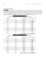
Page 12: ...6 0 6 0 6 120 120 120 120 up to 25 25 50 50 100 100 150 18 AWG 16 AWG 16 AWG 14 AWG 6 10 6 10 6 10 6 10 120 120 120 120 up to 25 25 50 50 100 100 150 18 AWG 16 AWG 14 AWG 12 AWG 10 12 10 12 10 12 10...

Page 13: ...WHEELS BUILT IN OPTIONAL MAX DEPTH OF CUT 1 4 MAX STOCK THICKNESS 8 MIN STOCK THICKNESS 1 4 MIN STOCK LENGTH 8 MAX STOCK WIDTH 16 FEED SPEED 16 28 FPM DUST PORT DIAMETER 4 LEFT AND RIGHT CUTTERHEAD RP...

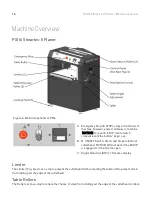
Page 14: ...button pops out B B ON OFF Switch Starts and Stops rotation of cutterhead NOTICE Will not work if the ESTOP is engaged or if the Hood is open C Digital Read Out DRO Thickness display Limiter The Limi...

Page 15: ...NG The feed speed selector offers two feed speeds 16 FPM 28 FPM Move lever push pull until it locks in place The middle setting is neutral Thickness Gauge The top of the planer is a Wixey thickness ga...

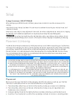
Page 16: ...OTED UPON DELIVERY AND SIGNED BY THE OWNER AND THE DELIVERY DRIVER IF YOU FIND ANY DAMAGED ITEMS IN YOUR PACKAGE YOU MUST CONTACT LAGUNA TOOLS TO FILE A COMPLAINT IN ORDER TO RETURN DAMAGED GOODS UNDE...

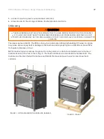
Page 17: ...THE PHYSICAL CAPABILITY OF ACHIEVING This step requires a forklift The PX16 is heavy be careful when lifting and handling it Failure to comply may cause serious injury and or damage to the machine and...

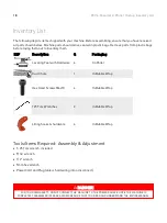
Page 18: ...ging Leveling Feet with Hardware 4 On Paller Dust Chute 1 In Bubble Wrap Hex Head Screws M6x10 4 In Bubble Wrap T25 Torx Wrenches 2 In Bubble Wrap Lifting hooks hardware 4 In Bubble Wrap Tools items R...

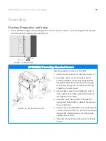
Page 19: ...mble swivel caster into swivel caster bracket straight bracket by placing bolt 5 through bracket and caster and securing with lock nut 4 Then place bolt 6 down through bracket into caster mount 3 Atta...

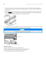
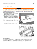
Page 20: ...t slightly above or flush with the table FIGURE 4 TABLE ROLLER ADJUSTMENT 4 The dust chute can be attached with the port facing either to the right or left To attach use four included screws Fig 5 H t...

Page 21: ...Single Phase 60 HZ AC current Confirm your motor electrical configuration before connecting power Before connecting the machine to the power source make sure the starter and switches are in the OFF po...

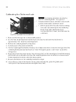
Page 22: ...is approximately 1 16 above the calibrating board 3 Remove the calibrating board from the planer 4 Connect power to the planer and turn ON 5 Turn the height adjustment handle clockwise one complete re...

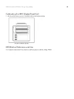
Page 23: ...ling Calibrating the DRO Digital Read Out 1 Remove the battery cover of the DRO and install 2 AAA batteries FIGURE 9 DRO BATTERIES DRO Button Reference and Use It is helpful to familiarize these butto...

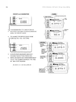
Page 24: ...24 PXl16 Sheartec II Planer Setup Assembling FIGURES 10 12 DRO ADJUSTMENT...

Page 25: ...ck into planer maintain control and support of stock until the stock is securely feeding through planer 7 Reposition yourself to the outfeed side of planer and control and support stock until it has e...

Page 26: ...It is a good idea to routinely inspect any quality woodworking tool in order to keep it in optimum condition This includes inspecting all hardware for tightness ensuring the filter is clean and clean...

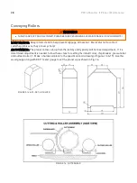
Page 27: ...rx wrench T25 to remove the knife insert screw Use a second Torx wrench to hold the cutterhead from rotating in position in another screw DO NOT USE YOUR HAND TO HOLD THE CUTTERHEAD See Fig 13 It is a...

Page 28: ...es as they are very sharp ADJUSTMENTS The planer comes set up from the factory and typically will not need adjustment If it is determined adjustment is needed follow these steps for setting the infeed...

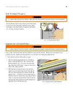
Page 29: ...ife Make sure the knives are set properly see the Setting Changing Knives section prior to making any adjustments 1 Disconnect machine from power source 1 Place a hard wood gauge Fig 17 A under a knif...

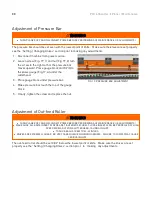
Page 30: ...Place gauge block under pressure bar 4 Make pressure bar touch the top of the gauge block 5 Finally tighten the screw and replace the nut FIG 19 PRESSURE BAR ADJUSTMENT Adjustment of Out feed Roller...

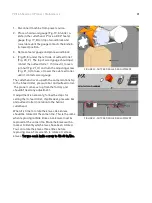
Page 31: ...erhead is set up with the same relationship to the infeed roller pressure bar and outfeed roller The planer comes set up from the factory and shouldn t need any adjustment If adjustment is necessary f...

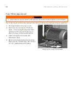
Page 32: ...needs adjustment 1 Disconnect machine from power source 2 Open lower rear and lower left hand side panels Loosen and tighten four adjustment nuts Fig 22 D to move motor plate up or down to increase or...

Page 33: ...ould be set at 0 If not adjust the pointer to read zero Note Spin the roller by hand to know when roller makes contact with the straight edge 3 Move straight edge to the opposite side of bed roller an...

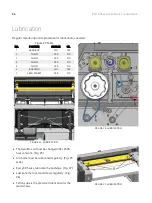
Page 34: ...CHAIN YES NO 5 CHAIN YES NO 6 BUSHING NO YES 7 LEAD SCREW YES NO FIGURE 26 LUBRICATION FIGURE 25 LUBRICATION The Gear Box oil must be changed after 2500 hours of work Fig 25 All chains must be lubric...

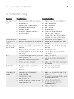
Page 35: ...ass 2 Chipbreaker or pressure bar set too low 3 Insufficient pressure on in feed or out feed rollers 1 Reduce the amount of material being removed 2 Raise the pressure 3 Increase pressure on in feed o...

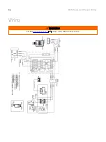
Page 36: ...36 PXl16 Sheartec II Planer Wiring Wiring WARNING REVIEW ELECTRICAL SAFETY PRIOR TO ANY WIRING PROCEDURES 9...

Page 37: ...37 PXl16 Sheartec II Planer Replacement Parts Diagram Replacement Parts Diagram Cutterhead Drivetrain...

Page 38: ...38 PXl16 Sheartec II Planer Replacement Parts Diagram Table Lift...

Page 39: ...39 PXl16 Sheartec II Planer Replacement Parts Diagram Stand Motor...

Page 40: ...X12 10 18 000103 103 CAP SCREW M6 1 0X12 26 19 174828 000 LIMIT PLATE 1 20 002102 201 FLAT HEAD PHILLIPS LOCK SCREW M4 0 7X10L 2 21 000301 101 ROUND HEAD PHILLIPS SCREW M3 0 5X6 4 22 300117 909 SWITCH...

Page 41: ...IDE 1 55 361382 902 ROD 2 56 361416 000 OUTFEED ROLLER 1 57 012006 001 KEY 8X8X40 1 58 925087 001 HELICAL CUTTERHEAD ASSY 1 922841 001 INSERTS 10PCS BOX 1 59 043343 000 RETAINING RING NBR 46 3 3 1 1 6...

Page 42: ...TER 1 84 006001 009 FLAT WASHER 5 2 10X1 0 2 85 174561 000 POINTER FIXING PLATE 1 86 006704 100 WAVES WASHER WW 12 2 87 361365 902 GUIDE BLOCK 2 88 361384 902 ROLLER SHAFT 2 89 030005 001 BALL BEARING...

Page 43: ...000 SPROCKET 2 131 016019 000 CHAIN 40 42P 1 132 000702 104 FLAT HEAD HEX SCREW M6 1 0X16 1 133 240092 000 HAND WHEEL 1 134 230284 000 FOLDING HANDLE HL 65 1 135 000103 105 CAP SCREW M6 1 0X15 8 136 0...

Page 44: ...X30 4 7 490124 000 TERMINAL COVER 1 8 003303 102 ROUND HEAD PHILLIPS SCREW 3 16 24X1 4 1 9 006502 100 TEETH WASHER 5 3 10 BW 5 2 10 000303 104 ROUND HEAD PHILLIPS SCREW M5 0 8X12 4 166 174820 000 SIDE...

Page 45: ...1 5 023701 007 RELIEF BUSHING MG25AS 14B 1 203 008006 800 HEX NUT M8 1 25P 13BX6 5H 4 204 014371 000 POLY BELT 560J 12 1 205 174823 000 SIDE COVER L 1 206 360579 902 SUPPORT PIN 1 207 280089 901 SPRI...

Page 46: ...PURCHASER MUST PRESENT THE ORIGINAL RECEIPT AS PROOF OF PURCHASE SHIPPING DAMAGE LAGUNA TOOLS AND THE PURCHASING CUSTOMER IS NOT RESPONSIBLE FOR DAMAGE OR LOSS CAUSED BY A FREIGHT COMPANY OR OTHER CI...

Page 47: ...47 PXl16 Sheartec II Planer Warranty...

Page 48: ...Carolina 825 Bistline Dr Ste 101 West Columbia SC 29172 U S A Phone 1 800 234 1976 Minnesota 5250 West 74th St Edina MN 55439 U S A Phone 1 949 474 1200 LAGUNA AMERICAN HEADQUARTERS LAGUNA EUROPE Walk...

Reviews: