31
PXl16 Sheartec:II Planer \ Maintenance
1. Disconnect machine from power source.
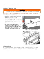
2. Place a hard wood gauge (Fig.17, A) under a
knife in the cutterhead. Place a 0.02” feeler
gauge (Fig. 17, B) on top of wood block and
raise table until the gauge contacts the knife in
its lowest position.
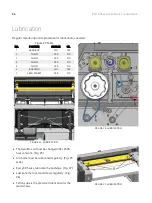
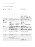
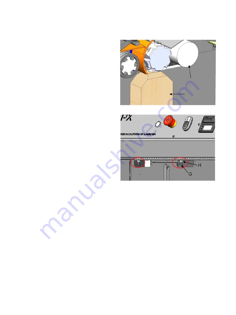
3. Remove feeler gauge and place wood block
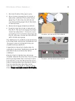
4. (Fig.20, E) under the left side of outfeed roller
(Fig. 20, F). The top of wood gauge should just
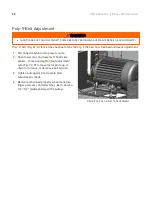
contact the outfeed roller. If it doesn’t, loosen
jam nut (Fig. 21, H) and turn the adjusting screw
(Fig. 21, G) to raise, or lower the out-feed roller
until it contacts wood gauge.
The cutterhead is set-up with the same relationship
to the infeed roller, pressure bar and outfeed roller.
The planer comes set up from the factory and
shouldn’t need any adjustment.
If adjustment is necessary, follow the steps for
setting the in-feed roller, chipbreaker, pressure bar
and outfeed roller in relation to the helical
cutterhead.
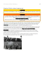
When it is time to rotate the knives ALL knives
should be rotated at the same time. This is the same
when replacing carbide knives ALL knives must be
replaced at the same time. Mark the knives with a
marker to identify which knives have been rotated.
You can rotate the knives three times before
replacing. Use a Torx wrench to rotate or remove
knives. Torque each knife screw to 52-60 in/lbs.
FIGURE 20: OUTFEED ROLLER ADJUSTMENT
FIGURE 21: OUTFEED ROLLER ADJUSTMENT
Summary of Contents for Sheartec:II PXl16
Page 1: ...PXl16 Sheartec II Planer Owner s Manual MPLANPX16 0130 3 10 2021...
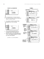
Page 24: ...24 PXl16 Sheartec II Planer Setup Assembling FIGURES 10 12 DRO ADJUSTMENT...
Page 38: ...38 PXl16 Sheartec II Planer Replacement Parts Diagram Table Lift...
Page 39: ...39 PXl16 Sheartec II Planer Replacement Parts Diagram Stand Motor...

