background image


Copyright © 2020 Laia · www.laiatech.com 

              All rights reserved 

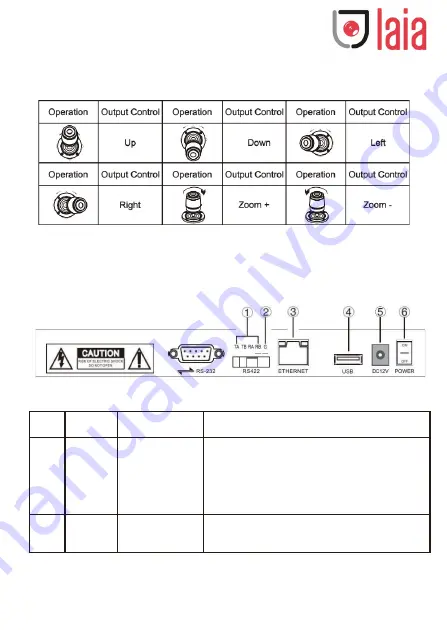
2.3  Rocker Control 

(clockwise/counterclockwise rotation is only valid for 3D)


2.4  Control keyboard rear interface terminal description 

Back panel: There is a 5PIN crimp terminal interface, an RS232 
interface, a DC-12V power plug, a USB interface, and a network port, 
as shown in the figure:


2.5  Function number description 


No.


Mark


Physical interface


Description


1


RS422


Control output (Ta, 

Ta, Ra, Rb)


Connect the RS422 bus of the camera; (TA) to the 
camera (RA), (TB) to the camera (RB), (RA) to the 
camera (TA), (RB) to the camera (TB).


Ground


Control signal line 

ground (G)


Control signal line ground


Summary of Contents for T-JOY-IP

Page 1: ...Copyright 2020 Laia www laiatech com All rights reserved T JOY IP...

Page 2: ...and keep it for future reference before using this product Preface The control keyboard is an indispensable device in the integrated monitoring system All the front end fastball pan tilt and electric...

Page 3: ...perate when you enter an IP address Because the keyboard does not have a button it is divided into four segments when inputting the IP for example to input 192 168 0 1 after inputting 192 168 it will...

Page 4: ...board and the dome are connected in the same LAN and the network segment where the IP address is located is consistent For example 192 168 1 123 and 192 168 1 111 belong to the same network segment 19...

Page 5: ...ion Four dimensional control up down left right rocker buttons and zoom function Interface Mode Lead mode Display Method LCD Beep Button sound prompt on off Working Power DC 12V 1A 10 inside and outsi...

Page 6: ...CUS AUTO Auto Focus button Design the camera to be in auto focus mode This case will light up when the camera is in manual focus mode AE AUTO Auto Iris button Set the camera to auto iris mode This but...

Page 7: ...enu MENU BACK Exit submenu CAM The CAM NUM set when IP VISCA or ONVIF mode input device is added can be quickly switched to the device bound to the CAM NUM In VISICA or PELCO the input address code sw...

Page 8: ...us FAR far focus OPEN CLOSE Manually adjust the aperture OPEN aperture plus CLOSED aperture reduction R R Manually adjust the red gain B B Manually adjust the blue gain PTZ SPEED PTZ SPEED Adjust PTZ...

Page 9: ...PIN crimp terminal interface an RS232 interface a DC 12V power plug a USB interface and a network port as shown in the figure 2 5 Function number description No Mark Physical interface Description 1 R...

Page 10: ...joystick can be switched from button sound to off ENTER key confirmation 1 Delete device 2 Network type dynamic static 3 Button sound on off 4 System language Chinese English 5 Mode VISCA IP VISCA ON...

Page 11: ...t the baud rate 9600 ENTER when the keyboard switches to address 1 the control baud rate is 9600 3 5 PELCO mode setting options Control settings set the baud rate of an address code The joystick switc...

Page 12: ...nd press ENTER to connect the device Login successfully displayed XXX XXX XXX XXX Note Enter the keyboard in any input state for confirmation the joystick to the left is BACKSPACE or DELETE 4 2 Connec...

Page 13: ...t the page is displayed as follows 4 After entering the device home page the three lists are search device list green box device list blue box added device details orange frame manual addition yellow...

Page 14: ...2 LAN Settings The LAN settings can modify the IP acquisition mode and port parameters of the device as shown in the following figure Dynamic address default access method the keyboard will automatica...

Page 15: ...off or disconnect the network 5 4 Restore Default When the device appears to be unable to work properly due to modification of some configurations this function can be used to restore the device to fa...

Reviews: