38
90028771rev00
INSTALLATION INSTRUCTIONS
After selecting and preparing the Oven/Steamer operating location, the oven/steamer
can be positioned and installed. When installation is complete, perform all start-up
checks to verify proper installation and operation.
POSITION AND LEVEL THE OVEN/STEAMER
NOTE: If there is not enough clearance behind the to install the drain, electrical, and
water lines, skip this procedure and continue with Install and Connect the Free Air
Vented Drain Lines. After installing all necessary drain, electrical, and water lines,
return to these instructions and install the unit.
The is positioned and leveled twice. First level the main unit in position.
Then place the roll-in cart in the cooking chamber, and adjust the unit level to match the
roll-in cart.
WARNING
Malfunctions and equipment damage may result from improper mounting.
Malfunctions and/or damage resulting from improper mounting are not covered by
the equipment warranty. The MUST BE LEVEL BOTH FRONT TO BACK AND SIDE TO
SIDE in all mounting arrangements.
Equipment damage may result from shifting the Oven/Steamer more than 3° out of
level while power is turned on.
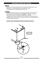
Adjustable Leveling Legs only if present
The supporting legs of the Oven/Steamer are 12 inch/304.8 mm long when the adjustable
feet are fully retracted. The adjustable feet can be extended approximately 2 inches/50.8
mm. This extension provides the 4 inch/101.6 mm space below the unit required by NSF
sanitary standards, and a means of leveling the oven/steamer.
ASSEMBLY
Check that the feet are fully retracted into the legs. Do not overtighten. The feet should
easily screw in and out using fingers only.
WARNING
INJURY AND EQUIPMENT DAMAGE could result from improper lifting. Refer to the
appropriate dimension and check the weight of the unit being installed.
Use enough workers with experience of lifting heavy equipment to place the on the
supporting surface.
Be sure electric power is turned off at the main power switch. Place the on the left
side.
1
-
2
-
Summary of Contents for Naboo Compact CBEN061
Page 2: ... 2 90028771rev00 ...
Page 20: ... 20 90028771rev00 INSTALLATION DIAGRAMS ...
Page 64: ... 64 90028771rev00 ...
Page 65: ... 65 90028771rev00 65 90028771rev00 ...
Page 66: ... 66 90028771rev00 66 90028771rev00 ...
Page 67: ......


