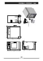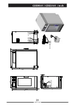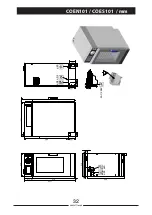
INSTALL AND CONNECT THE FREE AIR VENTED DRAIN LINES
WARNING
DEATH, INJURY, AND EQUIPMENT DAMAGE could result from improper installation
of the drain outlet lines.
Improper installation of these lines could void the warranty.
The following restrictions are critical to the safety of personnel and equipment, and
must not be violated under any circumstances.
Do not connect the drain line into PVC pipe, or any other drain material
that cannot sustain 180 °F/82 °C.
Do not connect drains from any other equipment to the Oven/Steamer drain line.
Do not connect the drain outlet extension line directly to a floor drain or sewer line.
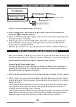
Do not block drain vents at the top of the unit (
).
The drain lines must be installed in compliance with the Basic Plumbing Code of the
Building Officials and Code Administrators International, Inc. (BOCA), and the Food
Service Sanitation Manual of the Food and Drug Administration (FDA).
The total length of pipe and number of bend fittings required to reach the open drain
determines the pipe size used to extend the drain line to an open drain.
• If the drain outlet extension requires twelve feet or less of pipe, and no more than two
elbows are required, use 2” / 50 mm pipe and fittings.
The drain line must have a gravity flow from the drain outlet to the floor drain. Do not
install a trap in the drain line.
Free air venting requires a minimum of 1”/25.4 mm clearance between the end of the
drain line and the top of the floor drain.
Do not connect the steamer drain to drains or plumbing of any other equipment.
If drains of two or more units are connected together:
• Low pressure can develop, causing an implosion and physical collapse of the
Oven/Steamer.
• Drainage from another unit can flow back into compartment of Oven/Steamer.
When assembling the drain pipes and fittings, apply a hardening type pipe sealant
to the threads, and thread them together FINGER TIGHT ONLY. DO NOT USE A WRENCH.
44
90028771rev00
1
-
2
-
3
-
4
-
5
-
6
-
Summary of Contents for Naboo Compact CBEN061
Page 2: ... 2 90028771rev00 ...
Page 20: ... 20 90028771rev00 INSTALLATION DIAGRAMS ...
Page 64: ... 64 90028771rev00 ...
Page 65: ... 65 90028771rev00 65 90028771rev00 ...
Page 66: ... 66 90028771rev00 66 90028771rev00 ...
Page 67: ......

