INSTALL AND CONNECT WATER SUPPLY LINES
Construct all supply lines up to the point of installing the strainer(s). Before connecting
the strainer(s), flush the water supply line(s). Then install the strainer(s) at the indicated
location(s).
• Make sure the arrow on the strainer body points in the direction of flow into the
oven/steamer fittings.
• Install the strainer so the access nut points down.
• If the remaining water lines and/or water trattament system are not installed and
connected immediately after flushing, temporarily cap the strainer outlet(s) to prevent
blockage.
Construct the remainder of the water supply lines but do not connect them to the Oven/
Steamer.
a.
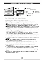
If the Oven/Steamer is installed with a water trattament system, refer to figure 2-7, and
the water trattament system manual for detailed instructions.
• The 40-mesh strainer must be installed at the water trattament system inlet.
• A check valve must be installed between the water trattament system and the
Oven/Steamer steam generator inlet.
• The line from the water trattament system must connect to the Oven/Steamer 3/4” steam
generator inlet.
b.
If the Oven/Steamer is installed without a water trattament system, refer to Figure 2-6.
Note that the tee is installed after the check valve and strainer to reduce the number
of fittings and amount of piping required.
Before connecting the water supply lines to the Oven/Steamer, flush the lines.
Then connect the water supply lines to the at the locations shown in the appropriate
dimension drawing (Figure 2-2).
TESTING WATER SUPPLY LINES
Check all connections for proper tightness.
Remove the right side access panel to inspect water connections inside the steamer.
Open the water supply valves.
Check all lines and connections for leakage, both inside and outside the oven/steamer.
If no other inspections are being made at this time, replace the right side access panel.
INSTALL AND CONNECT GAS SUPPLY LINE
Furnishing and installing the gas supply lines, valves, regulators, and accessories is
the responsibility of the owner and/or installer. When installing the gas supply lines and
accessories, observe the following instructions.
Install the gas supply lines in accordance with local codes and/or the National Fuel Gas
Code, ANSI Z223.1-(latest edition), the Natural Gas Installation Code CAN/CGA-B148.1 and
Propane Installation Code CAN/CGA-B148.2.
Use 1/2 inch gas supply piping and fittings. Refer to the appropriate dimension drawing for
pressure data and connection locations.
Refer to Figure 2-8 for recommended layout of the gas supply lines.
50
90028771rev00
6
-
7
-
1
-
2
-
3
-
4
-
1
-
2
-
Summary of Contents for Naboo Compact CBEN061
Page 2: ... 2 90028771rev00 ...
Page 20: ... 20 90028771rev00 INSTALLATION DIAGRAMS ...
Page 64: ... 64 90028771rev00 ...
Page 65: ... 65 90028771rev00 65 90028771rev00 ...
Page 66: ... 66 90028771rev00 66 90028771rev00 ...
Page 67: ......


