background image

https://www.lairdconnect.com/ 

34 

© Copyright 2020 Laird Connectivity.  

All Rights Reserved 

Americas

: +1-800-492-2320 

Europe

: +44-1628-858-940 

Hong Kong

: +852 2923 0610 


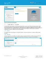
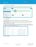
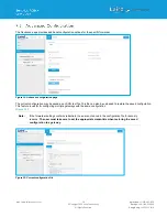
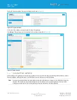
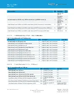
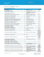
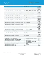
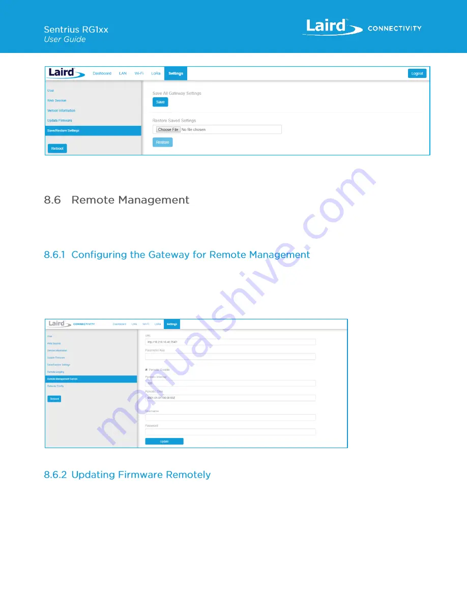
Figure 44: Save/Restore settings 

After restoring settings, the gateway must be rebooted for changes to take effect. 


The gateway can be managed remotely via TR-069. It requires an externally hosted Auto Configuration Server (ACS) to use 
this feature. This allows a system administrator to access the gateways without needing physical access to the gateway or 
access behind a firewall. The gateway will periodically initiate connections with the ACS allowing a user to remotely update 
LoRa configuration settings, update firmware, download logs, etc. 


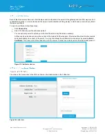
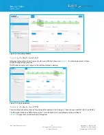
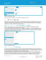
The user must point the device to your external ACS. This is done under 

Settings > Remote Management Service

.  

This is a one-time setting that is preserved across firmware updates.  
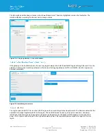
The URL must be updated, including the port number. In a standard ACS installation, this is usually 

port 7547

 but that can 

vary. Consult your ACS provider for the URL, port number, username, and password. The username and password fields are 
for connections initiated by the gateway. Not for connections initiated by the ACS. The parameter key is optional. Press the 
update button when all parameters are correctly entered. 


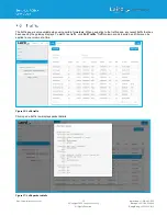
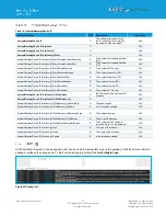
Figure 45: Save/Restore settings 


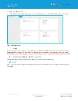
This works much like it does with the web User Interface (UI). When the system administrator has a new firmware release to 
load, they will update the InternetGatewayDevice.Laird.GatewayManagement.Versions.FirmwareUpdateURL. The value is the 
link to download the firmware. This link always points to a fw.txt file. Once that is done, the gateway will respond with success, 
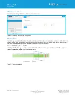
and download the firmware in the background. A remote user would then poll for 
InternetGatewayDevice.Laird.GatewayManagement.Versions.FirmwareUpdateStatus 

to be set to “1” indicating that the 

firmware was successfully downloaded and is ready to reboot to switch to the new firmware. The system administrator would 
then issue the TR-

069 “Reboot” command to reboot the device. After the reboot, the gateway will check in again and be 

running the new version. Note that settings (including remote management) are preserved across a firmware update. 

Summary of Contents for 450-0190

Page 1: ...Version 4 1 ...

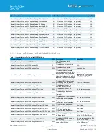
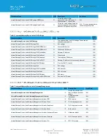
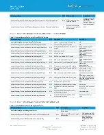
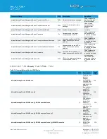
Page 2: ...vailable firmware version Updated to new template Jonathan Kaye 3 2 29 Mar 2018 Removed inapplicable Firmware update URLs Sue White Jonathan Kaye 3 3 13 Apr 2018 Important update to firmware upgrade procedure Ryan Erickson Shewan Yitayew 3 4 30 May 2018 Updates for GA3 firmware Add section for web session timeout Update firmware upgrade section Ryan Erickson Jonathan Kaye 3 5 20 Aug 2018 Updated O...

Page 3: ...Profile 17 6 3 Wi Fi Advanced Page 18 7 LoRa Connection Setup 19 7 1 Using Presets 19 7 2 Semtech Basic Station 20 7 2 1 Mode 20 7 2 2 Servers 20 7 2 3 Certificates 21 7 2 4 Connection Status 21 7 3 Senet 22 7 4 Semtech Legacy UDP Forwarder 22 7 5 Advanced Configuration 28 7 6 Traffic 29 8 Manage the Gateway 30 8 1 Changing Username and Password 30 8 2 Web Session 30 8 3 Version Information 31 8 4...

Page 4: ...ssemblies 49 9 5 Mounting Hardware 51 10 FCC and ISED Canada Regulatory Statements 53 11 CE Regulatory 55 11 1 EU Declarations of Conformity 55 12 Taiwan NCC Regulatory 56 13 Telecommunications Regulatory Authority TRA Compliance 56 14 Region Supported Labels 57 14 1 RG191 Version 57 14 2 AU915 AS923 Regions 57 14 2 1 Taiwan TW 57 14 2 2 New Zealand NZ 57 14 2 3 Hong Kong HK 58 14 2 4 Australia AU...

Page 5: ...ateway is the ultimate in secure scalable robust LoRa solutions for end to end control of your private LoRaWAN network Leveraging Laird s field proven and reliable 50 Series Wireless Bridge certified module it also offers enterprise dual band Wi Fi and wired Ethernet for complete design freedom Based on the Semtech SX1301 SX1257 chipset designs it offers a LoRa range up to ten miles and pre loaded...

Page 6: ... 11a UNII 1 UNII 2A UNII 2C or CH 36 CH140 6 Mbps 17 dBm 54 Mbps 14 dBm 802 11a UNII 3 or CH 148 CH 165 6 Mbps 15 dBm 54 Mbps 14 dBm 802 11b 1 Mbps 17 dBm 11 Mbps 17 dBm 802 11g 6 Mbps 17 dBm 54 Mbps 14 dBm 802 11n 2 4 GHz 6 5 Mbps MCS0 17 dBm 65 Mbps MCS7 13 dBm 802 11n 5 GHz UNII 1 UNII 2A UNII 2C or CH 36 CH140 6 5 Mbps MCS0 HT20 17 dBm 65 Mbps MCS7 HT20 13 dBm MCS0 HT40 14 dBm MCS7 HT40 11 dBm...

Page 7: ...y in Radio TX Power Table AUS 27 dBm max entry in Radio TX Power Table AU915 and AS923 TWN 25 dBm max entry in Radio TX Power Table HK 25 dBm max entry in Radio TX Power Table MY 25 dBm max entry in Radio TX Power Table SG 27 dBm max entry in Radio TX Power Table US NZ AUS TWN HK MY SG 0 dBm min entry in Radio TX Power Table LoRa Radio Conducted RX Sensitivity RG191 plus AS915 AU923 variants 127 d...

Page 8: ...0 to 85 C Regulatory Approvals RG186 CE Health and Safety IEC 60950 1 V2 0 Radio EN300 220 1 V3 1 1 2017 02 EN300 220 2 V3 1 1 2017 02 EMC EN301 489 1 V2 2 0 2017 03 EN301 489 3 V2 1 1 2017 03 Approvals RG191 FCC Contains FCC ID SQG WB50NBT IC Contains IC ID 3147A WB50NBT FCC Contains FCC ID SQG 1001 IC Contains IC ID 31347A 1001 NZ AS NZS 4268 2017 AUS AS NZS 4268 2017 TWN NCC LP0002 Malaysia TBC...

Page 9: ...aWAN Wi Fi and Ethernet UK Power Adapter 450 0190 Sentrius RG191 US US902 928 915 MHz Gateway LoRaWAN Wi Fi and Ethernet IP67 450 0191 Sentrius RG186 Europe EU868 868 MHz Gateway LoRaWAN Wi Fi and Ethernet IP67 455 00054 Sentrius RG191 New Zealand AS923 923 MHz Gateway LoRaWAN Wi Fi and Ethernet NZ Power Adapter 455 00055 Sentrius RG191 Hong Kong AS923 923 MHz Gateway LoRaWAN Wi Fi and Ethernet HK...

Page 10: ...Configuration for additional information 2 Connect the power supply see 2 in Figure 3 3 Connect the gateway to your router 3 in Figure 3 using the Ethernet cable 1 in Figure 3 Alternatively use the Wi Fi Quick Config mechanism Refer to Wi Fi Quick Configuration for additional information Your gateway is now connected and ready Figure 3 Connecting the gateway To configure the antenna properly do th...

Page 11: ...gure 4 The network is secured with WPA2 with a password that is the same as the SSID We recommend that you change the default password for security reasons The password can be changed on the Wi Fi Advanced web page Upon logout or client disassociation Wi Fi Quick Config shuts down and normal operation resumes To log into the gateway web interface follow these steps 1 Determine the last three bytes...

Page 12: ...ericas 1 800 492 2320 Europe 44 1628 858 940 Hong Kong 852 2923 0610 Figure 5 Web interface first screen 5 Click Proceed Figure 6 Figure 6 Web interface second screen 6 Log on using the following default credentials Username sentrius Password RG1xx Figure 7 Gateway interface login screen ...

Page 13: ...er logging in the program warns you to change the default credentials for security reasons Figure 8 Figure 8 Change the default credentials Only one login session is allowed at a time If there is another active session active the program warns you before allowing you to take over the session Figure 9 Figure 9 Active session warning 7 Click Continue to log in ...

Page 14: ...nfiguration settings except IP Address Acquisition Method are greyed out IP values provided by DHCP are displayed but cannot be changed Static When the IP Address Acquisition Method is set to static all IP settings are fixed and saved in the device The external Gateway IP address is optional and may be left blank DNS Server IP addresses are also optional Zero one or two DNS servers may be specifie...

Page 15: ... the advanced view by clicking the Advanced menu item in the LAN sidebar Figure 12 The Advanced view shows all network information provided by the Wi Fi module in the gateway Depending on the settings of the network and the gateway not all settings may apply to the current mode of operation This view is intended to support advanced users in troubleshooting their network Figure 12 Advanced view ...

Page 16: ...setup a Wi Fi connection click the Wi Fi tab in the main menu Figure 13 Figure 13 Wi Fi connection setup In the sidebar on the left you can navigate to various Wi Fi pages and see the status of the Wi Fi interface There is also a button to enable disable the Wi Fi radio To use the scan function to add a profile follow these steps Connect to a Wi Fi network click Scan to scan for nearby Wi Fi netwo...

Page 17: ...i profile window To add a Wi Fi network profile manually follow these steps Click the LAN button in the main menu then click the Profiles button in the left menu This page is useful for adding a hidden Wi Fi network that is not broadcasting its SSID Figure 16 Figure 16 Wi Fi profiles page The profile page shows all Wi Fi profiles that are saved in the gateway You can add activate or delete the pro...

Page 18: ...28 858 940 Hong Kong 852 2923 0610 Figure 17 Wi Fi profile dialog Enter the appropriate information for the new profile Click Add The Wi Fi advanced page shows more detailed information about the Wi Fi radio status and allows the user to configure the Quick Config AP mode password Figure 18 Figure 18 Wi Fi Advanced page ...

Page 19: ...Right The SentriusTM RG1xx contains multiple preset configurations for connecting to a third party server or as the basis for a private network These presets configure the forwarder and the channel plan To apply a preset configuration follow these steps Click the LoRa tab in the main menu The default page of the LoRa menu is the Presets page also accessible in the left side menu of the LoRa pages ...

Page 20: ...ce to configure the LNS connection remotely All configuration settings beyond this are handled by the Lora Network Server This includes the channel plan An appropriate channel plan must be selected in the LNS that corresponds to the region of operation for your specific gateway The forwarder page allows configuration of the packet forwarder The mode allows the user to change to different packet fo...

Page 21: ...w these steps Click Choose File Select the desired pem file and press upload You can optionally select to upload your client certificate and key files when necessary All files can be uploaded at once with one click of the Upload Certificate button After upload the Basic Station restarts and should attempt to connect to the server You may also delete the certificates for each server by pressing Del...

Page 22: ...peration Senet DEV and Senet RAN In Senet DEV mode the web UI is enabled When in Senet RAN mode the Web UI is disabled and the only way out of that mode is by performing a factory reset see Factory Reset section After a factory reset you must contact Senet to be able to reconnect the gateway with the same EUI Click Forwarder in the left hand menu of the LoRa pages to access the Forwarder settings ...

Page 23: ...uration of the radios and channels The LoRa card has two radios Radio 0 and Radio 1 This interface allows advanced users to change radio and channel assignments within the allowed range per the gateway region Depending on the forwarder being used the radio configuration may not be available At the top of the Radios page is a graphic representation of the full bandwidth range channels and radios Th...

Page 24: ...nel s frequency is an offset of its radio s center frequency For most channels with a 125 kHz bandwidth the offset can be 0 4 to 0 4 MHz LoRa STD and FSK channels have configurable bandwidth For these channels when operating in 250 kHz or 500 kHz bandwidth the offset can be 0 3 to 0 3 MHz Each channel should be placed at least 200 kHz from any other channel otherwise the channel s bandwidth overla...

Page 25: ...In Figure 31 the allowed placement of these channels displays larger and blue If a 500 kHz channel is not configured the interface displays a warning Figure 31 US region gateways There are three mandatory channels for gateways that operate in the EU region These channels are 868 1 868 3 and 868 5 The EU region bands have different duty cycles This is indicated with a grey background box and label ...

Page 26: ...ough the web UI on the gateway A factory reset must be performed on the device after toggling between AU915 and AU923 No other regions are end user selectable Figure 33 Australia region selector The region code is AU915 This is not an AS923 region with no mandatory channel requirements The firmware will restrict the operation to the legal regulatory limits for this region These limits include freq...

Page 27: ...anner the packet will be dropped In the case of TX power the TX power will be clipped to the highest allowable power if the requested power exceeds the legal limit for this region The region code is HK This is an AS923 region therefore there are two mandatory channels 923 2 and 923 4 The firmware will restrict the operation to the legal regulatory limits for this region These limits include freque...

Page 28: ...e current configuration may be saved as a JSON text file This file can also be uploaded to restore the saved configuration This feature is useful for configuring multiple gateways with the same configuration Figure 35 Note If the forwarder settings contain credentials these are not saved in the configuration file for security reasons The user must take care to set the appropriate credentials when ...

Page 29: ...e is only available when using certain forwarders When navigating to the traffic page any recent traffic that has been seen by the gateway displays To watch live traffic click Poll Traffic Traffic columns can be sorted and filters can be applied to one column at a time Figure 36 LoRa traffic Clicking on a traffic row displays packet details Figure 37 LoRa packet details ...

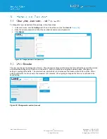
Page 30: ...ord Click Update Figure 38 Change username and password The user can change the web session timeout The web session timeout is the amount of time before the user will be warned and automatically logged out if there is no web activity Activity is defined as navigating between pages changing any settings or polling LoRa traffic The minimum time and default is 5 minutes and the maximum time is 60 min...

Page 31: ...lick Update Firmware in the left menu Enter the proper URL Information about what URL to used can be found below Click Start Update Warning Updating the firmware MAY restore the gateway to factory default settings We advise you to save or make note of any settings the user does not wish to lose beforehand IMPORTANT Please follow the instructions based on the firmware version currently running on t...

Page 32: ... link the gateway will be running version 93 7 2 10 Follow the instructions for that version to update to the latest version of firmware WARNING This upgrade performs a factory reset on the gateway If the gateway is running version 93 7 2 10 firmware the user should use this link to upgrade to the next version https www lairdtech com products rg1xx lora gateway firmware newest fw txt Note This req...

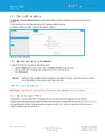
Page 33: ...o take effect Figure 43 Figure 43 Reboot prompt All the settings in the gateway can be saved and restored This is useful for backing up all settings before a factory reset or firmware upgrade Settings are saved to a JSON file and can be restored on another gateway Note Any security related settings like credentials and security certificates are not saved in the JSON file for security reasons That ...

Page 34: ...r ACS provider for the URL port number username and password The username and password fields are for connections initiated by the gateway Not for connections initiated by the ACS The parameter key is optional Press the update button when all parameters are correctly entered Figure 45 Save Restore settings This works much like it does with the web User Interface UI When the system administrator ha...

Page 35: ...a larger group of deployed units This file will include LoRa settings Wi Fi settings and IP settings This includes the channel plan used by the Semtech UDP packet forwarder This file can be uploaded to deployed gateways to update their configuration to match the device that was updated locally It is always good practice to locally test any configuration changes you make so that you know it works t...

Page 36: ...2 psk wpa2 aes cckm tkip cckm aes wpa psk aes wpa aes InternetGatewayDevice Laird ActiveProfileSettings Mode R W Wi Fi network mode BGN InternetGatewayDevice Laird ActiveProfileSettings Powersave R Is power save enabled off max fast InternetGatewayDevice Laird ActiveProfileSettings PSPDelay R Power save delay A value 10 500 in milliseconds InternetGatewayDevice Laird ActiveProfileSettings Username...

Page 37: ... LORASettings Region R W This is the region of operation your gateway is configured to It is only writable one time and is set before leaving the factory Attempting to change this after it is locked will result in no change and an error being returned The following strings representing country codes MY SG TW HK AU915 AU923 NZ US EU InternetGatewayDevice Laird LORASettings STServer R W This is the ...

Page 38: ...ice Laird LANSettings IPv4 ExtGWIP R Gateway IP address not necessarily external N A InternetGatewayDevice Laird LANSettings IPv4 IPMethod R IP mode DHCP or static N A InternetGatewayDevice Laird LANSettings IPv6 O IPv6 settings N A InternetGatewayDevice Laird LANSettings IPv6 DeviceAddr R IPv6 address N A InternetGatewayDevice Laird LANSettings IPv6 Mask R IPv6 net mask N A InternetGatewayDevice ...

Page 39: ...t name for the selected Wi Fi profile String representing name client name InternetGatewayDevice Laird SavedProfileSettings TxPower R W TX power for the selected Wi Fi profile A numeric value representing TX power InternetGatewayDevice Laird SavedProfileSettings AuthType R W Authentication type for the selected Wi Fi profile open shared or eap InternetGatewayDevice Laird SavedProfileSettings EAPTy...

Page 40: ...assword used for the ACS to initiate a connection with the gateway String representing the password for connections initiated by the ACS InternetGatewayDevice ManagementServer Username R W Username for the gateway to initiate a connection with the ACS String representing the username for connections initiated by the gateway InternetGatewayDevice ManagementServer URL R W URL for the gateway to init...

Page 41: ...evice IPPingDiagnostics Timeout R Diagnostic data for the IP connections N A InternetGatewayDevice IPPingDiagnostics DataBlockSize R Diagnostic data for the IP connections N A InternetGatewayDevice IPPingDiagnostics SuccessCount R Diagnostic data for the IP connections N A InternetGatewayDevice IPPingDiagnostics AverageResponseTime R Diagnostic data for the IP connections N A InternetGatewayDevice...

Page 42: ... Enable R W Whether not SSID is enabled true false InternetGatewayDevice WiFi SSID x Status R SSID status N A InternetGatewayDevice WiFi SSID x Name R W SSID profile name The profile name string InternetGatewayDevice WiFi SSID x LowerLayers R W Reference to the radio in the data model Reference in the data model to the active radio string InternetGatewayDevice WiFi SSID x SSID R W SSID SSID for yo...

Page 43: ...ate password A string representing the certificate path InternetGatewayDevice WiFi EndPoint x Profiles y Security PACName R W PAC file name A string representing the PAC name InternetGatewayDevice WiFi EndPoint x Profiles y Security PACPassword W The PAC file password A string representing the PAC password InternetGatewayDevice WiFi EndPoint x Profiles y Enable R W Whether not the profile is enabl...

Page 44: ...tewayDevice IP Interface x Stats BytesSent R The number of bytes TX N A InternetGatewayDevice IP Interface x Stats ErrorsSent R The number of TX errors N A InternetGatewayDevice IP Interface x IPv4Address O IPv4 Settings for the particular IP interface N A InternetGatewayDevice IP Interface x IPv4Address y O N A InternetGatewayDevice IP Interface x IPv4Address y SubnetMask R The subnet mask N A In...

Page 45: ...shing release the user button The factory defaults are applied the gateway reboots and it is ready to use At this time the Bluetooth and Bluetooth Low Energy functionality onboard the RG1xx Gateway is not enabled Please visit the RG1xx page on Lairdconnect com for more information https www lairdconnect com wireless modules lorawan solutions sentrius rg1xx lora enabled gateway wi fi bluetooth ethe...

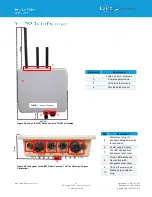
Page 46: ... Power supply module 3 CAT6 Ethernet module 4 Moulded plastic cover Figure 49 Side panel of the IP67 Rated Sentrius RG1xx Gateway Current Generation Ref Description 5 Metal cover plug 2 Available data power ports for expansion 6 Power supply module 7 Six LED displays with transparent dust cover 8 Three LED display and User button with transparent dust cover 9 CAT6 Ethernet module 10 Plastic gore v...

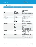
Page 47: ...0 x 70 mm enclosure only Environmental Operating Temp 40 to 85 C Wi Fi Antenna Model Laird 001 0012 IP67 rated Type Dipole Connector RP SMA Antenna Gain 2 0 dBi 2 4 2 5 GHz 2 0 dBi 4 9 5 875 GHz LoRa Antenna Model Laird 001 0029 IP67 rated 863 870 MHz used with RG186 Laird 001 0011 IP67 rated 902 928 MHz used with RG191 Type Dipole Connector RP SMA Antenna Gain 2 0 dBi 863 870 MHz used with RG186 ...

Page 48: ...8 940 Hong Kong 852 2923 0610 Figure 50 LED displays with User button 6 from Figure 49 Reference Description 1 Power green 2 LoRa green 3 BLE green 4 User Button Figure 51 Six LED display 7 from Figure 49 Reference Description 1 Power 2 Ethernet 3 Wi Fi 4 N A 5 User 6 N A Future Use Note All LEDs are green 1 2 3 4 1 2 3 4 5 6 ...

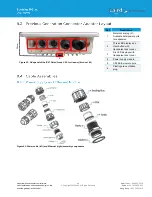
Page 49: ...10 Figure 52 Side panel of the IP67 Rated Sentrius RG1xx Gateway Revision 1 2 Ref Description 1 Metal cover plug 2 Available data power ports for expansion 2 Three LED display and User button with transparent dust cover 3 Six LED displays with transparent dust cover 4 Power supply module 5 CAT6 Ethernet module 6 Plastic gore ventilation plug Figure 53 Power cable left and Ethernet right assembly c...

Page 50: ... sealing body iv gasket v and lock nut vi Figure 54 Figure 54 Insert Ethernet cord Note To ensure the IP67 rating the cable diameter must be in the range of 5 5 mm 8 0 mm If the cable is too small there is a potential risk of environment factors potentially damaging the internal hardware Use a 1 5 mm screwdriver preferably an allen wrench to fix the core wire s into the screw fixing point Figure 5...

Page 51: ... with a torque force of 8 10 kgf cm Figure 57 Figure 57 Step 5 The assembly is now complete Figure 58 Figure 58 Completed assembly Mount the completed cables into the keyed power module slot and the Ethernet module slot 8 and 9 from Figure 49 Figure 59 Wall Mount Included Mounting Hardware M6x0 8x10 0 mm stainless steel screws with washers 4 5 16 x 11 self tapping screws L 25 00 mm 4 3 4 wall anch...

Page 52: ...2714 1166 Figure 61 Enclosure placement dimensions mm Figure 62 Pole mount pole diameter range 34 mm 90 mm Included Mounting Hardware M6x0 8x10 0 mm stainless steel screws with washers 4 5 16 x 11 Self tapping screws L 25 00 mm 4 3 4 wall anchors 4 M8x1 25x80 0 mm stainless steel screws with washers 2 M8x1 25x90 0 mm Stainless Steel Screws with washers and nut 1 M5x1 0mm Stainless Steel Screws L 1...

Page 53: ...ll persons and operating in conjunction with any other antenna or transmitter except in accordance with FCC multi transmitter product procedures WARNING Changes or modifications not expressly approved by Laird could void the user s authority to operate the equipment This equipment has been tested and found to comply with the limits for a Class B digital device pursuant to Part 15 of the FCC Rules ...

Page 54: ...ns suivantes 1 l appareil ne doit pas produire de brouillage et 2 l utilisateur de l appareil doit accepter tout brouillage radioélectrique subi même si le brouillage est susceptible d en compromettre le fonctionnement To comply with ISED Canada RF exposure limits for general population uncontrolled exposure the antenna s used for this transmitter must be installed to provide a separation distance...

Page 55: ...a Health and Safety EN60950 1 2006 A2 2013 3 1b Protection requirements Electromagnetic compatibility EN 301 489 1 v2 2 0 2017 03 EN 301 489 3 v2 1 1 2017 03 EN 301 489 17 v3 2 0 2017 03 3 2 Means of the efficient use of the radio frequency spectrum ERM EN 300 220 1 v3 1 1 2017 02 EN 300 220 2 v3 1 1 2017 02 EN 300 328 v2 1 1 2016 11 EN 301 893 v2 1 1 2017 05 Declaration We Laird declare under our...

Page 56: ...作業之無線電通信 低功率射頻電機須忍受合法通信或工業 科學及醫療 用電波輻射性電機設備之干擾 The RG186 has been tested for compliance with the relevant standards for the United Arab Emirates UAE market The RG186 will contain the following information on the back of the gateway serial number label Registered No ER61585 18 Registration number allocated by the TRA to the equipment RG186 TRA Registered Number ER61585 18 Dealer No DA72940 18 Deale...

Page 57: ...s the base for all current country variants Figure 65 RG191 Region Supported Label All region gateways will have a unique Product ID label which describes the region any region certification label requirements and frequency the gateway supports This label is placed in the blue border shown in Figure 65 All labels are printed in black and white color Figure 66 Taiwan 923MHz Region Supported Label F...

Page 58: ...s Reserved America 1 919 597 7300 Europe 46 31 420530 Asia 86 755 2714 1166 Figure 68 Hong Kong 923MHz Region Supported Label Figure 69 Australia 915 or 923MHz Region Supported Label Frequency changes depending on setting Figure 70 Singapore 923MHz Region Supported Label Pending Certification Figure 71 Malaysia 923MHz Region Supported Label Pending Certification ...

Page 59: ...Mouser Electronics Authorized Distributor Click to View Pricing Inventory Delivery Lifecycle Information Laird Connectivity 455 00102 455 00097 ...

Reviews: