www..lairdconnect.com/wireless
19
© Copyright 2020 Laird Connectivity. All Rights Reserved
Americas
: +1-800-492-2320
Europe
: +44-1628-858-940
Hong Kong
: +852 2923 0610
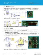
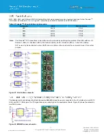
SW1, SW2, SW3, and SW4 are SPST-NO tact switches that when pressed provide a low logic level input to the Pinnacle
TM
100 modem as indicated in
shows the push button schematics and DVK locations.
Table 6: Pinnacle
TM
100 push button signal mapping
Designator
M2.#
NRF Port Name
SW1
M2.16
P0.31
SW2
M2.61
P0.03
SW3
M2.23
P0.04
SW4
M2.59
P0.02
Note:
The Pinnacle
TM
100 connections to the buttons can be removed by switching the positions of the DIP switches
– S4
Position 1 (SW1), S1 Position 6 (SW2), S3 Position 6 (SW3), and S1 Position 5 (SW4)
– to the OFF position.
SW1 is used by the bootloader to enter UART mode, so that must be considered if a user wants to use it for another
purpose.
Figure 21: Push button schematic
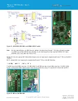
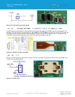
The development board includes the Bosch Sensortec BME680 air quality sensor connected to the I
2
C interface bus via M2.10
(SCL) and M2.11 (SDA) pins. The I
2
C signal traces are pulled high on the development board. Figure 22 shows the schematic
and DVK location.
Figure 22: BEM680 sensor schematic
Summary of Contents for 453-00010-K1
Page 1: ...Version 1 0 ...


