S E R I A L I N T E R F A C E
1 0
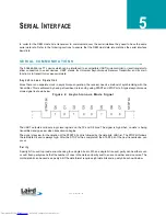
supported. For a baud rate to be valid, the calculated baud rate must be within ±3% of the OEM Host baud rate. If the
Test pin (Pin 12) is pulled logic Low at reset, the baud rate will be forced to 9,600.
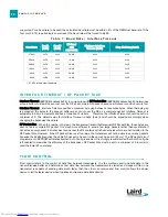
I N T E R F A C E T I M E O U T / R F P A C K E T S I Z E
Interface Timeout (EEPROM address 0x58), in conjunction with RF Packet Size (EEPROM address 0x5B), determines
when a buffer of data will be sent out over the RF as a complete RF packet, based on whichever condition occurs first.
Interface Timeout – Interface Timeout specifies a maximum byte gap between consecutive bytes. When that byte gap
is exceeded, the bytes in the transmit buffer are sent out over the RF as a complete packet. Interface Timeout is
adjustable in 0.5ms increments and has a tolerance of ±0.5ms. Therefore, the Interface Timeout should be set to a
minimum of 2. The default value for Interface Timeout is 0x04 (2ms) and should be adjusted accordingly when
changing the transceiver baud rate.
RF Packet Size – When the number of bytes in the transceiver transmit buffer equals RF Packet Size, those bytes are
sent out as a complete RF packet. It is much more efficient to send a few large packets rather than several short
packets as every packet the transceiver sends over the RF contains extra header bytes which are not included in the
RF Packet Size. However, if the RF Packet Size is set too large, the transceiver will not be able to send any packets
because the AC4868 requires the entire RF packet to be sent in the same hop period (53 ms). The RF packet size if
programmed in EEPROM automatically when Auto Config is enabled. It is strongly recommended that Auto Config be
left enabled to maximize the efficiency of the transceiver. RF Packet Size must be set to a minimum of 6 in order to
send the Enter AT command.
F L O W C O N T R O L
Flow control refers to the control of data flow between transceivers. It is the method used to handle data in the
transmit/receive buffer and determines how data flow between the transceivers is started and stopped. Often, one
transceiver is capable of sending data much faster than the other can receive and flow control allows the slower
device to tell the faster device when to pause and resume data transmission.
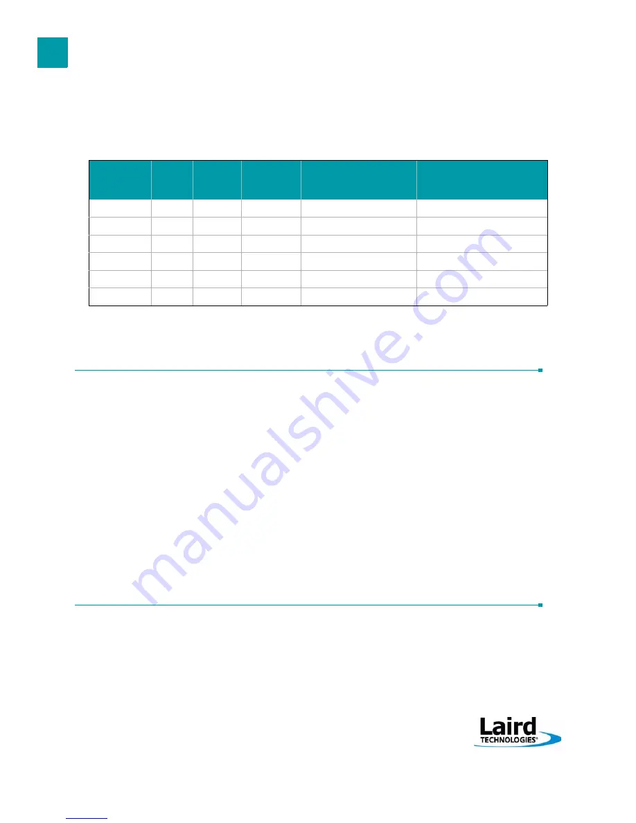
T a b l e 7 : B a u d R a t e / I n t e r f a c e T i m e o u t
Baud Rate
BaudL
(0x42)
BaudH
(0x43)
RF Baud
(not
adjustable)
Minimum Interface
Timeout (0x58)
Stop Bit Delay (0x3F)
57,600
1
1. 57,600 is the default baud rate
0xFC
0x00
28,800
0x02
0x03
38,400
0xFA
0x00
19,200
0x02
0x08
28,800
0xF8
0x00
28,800
0x02
0x0E
19,200
0xF4
0x00
19,200
0x03
0x19
14,400
0xF0
0x00
28,800
0x04
0x23
9,600
0xE8
0x00
19,200
0x05
0x39
electronic components distributor


