BL652 Development Kit
User Guide
Embedded Wireless Solutions Support Center:
http://ews-support.lairdtech.com
www.lairdtech.com/bluetooth
23
© Copyright 2016 Laird. All Rights Reserved
Americas: +1-800-492-2320
Europe: +44-1628-858-940
Hong Kong: +852 2923 0610
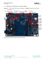
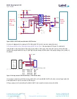
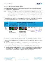
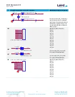
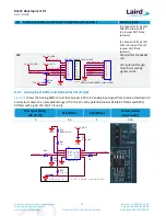
Plated Through Holes or Header Connector
BL652 Module Signals Exposed
J1
Serial Port plated holes for
access
J35
Jumper in J35 selects between
BL652 UART routed to FTDI or
Arduino:
No Jumper on J35 (default)
Routes SIO_5 (RTS) to FTDI CTS
Routes SIO_6 (TX) to FTDI RX
Routes SIO_7 (CTS) to FTDI RTS
Routes SIO_8 (RX) to FTDI TX
Jumper on J35
Routes SIO_5 (RTS) to TP10
Routes SIO_6 (TX) to Arduino
D1_TX
Routes SIO_7 (CTS) to TP11
Routes SIO_8 (RX) to Arduino
D0_RX
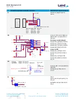
J12
Connects SIO_13 (nAutoRUN) to
FTDI DTR
Default jumper fitted in J12
pin 2-3
J5
SIO_ 2
Can be used to pull-up SIO_2 to
VCC_IO
Default No Jumper fitted on J5
SIO_2
SIO_6
R1
NOPOP (0R)
SIO_7
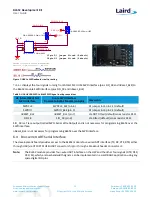
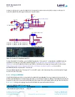
Module pin BL652 UART Data Flow
SIO_6 Module_TX Output
SIO_8 Module_RX Input
SIO_5 Module_RTS Output
SIO_7 Module_CTS Input
VCC_IO_UART
SIO_8
SIO_5
FTDI (USB to TTL 232 Cable)
GND
RTS
VCC
RX
TX
CTS
GND
USB_CTS
VCC
USB_TX
USB_RX
USB_RTS
J1
NOPOP (PIN HEADER,2.54mm 1X6P)
1
1
2
2
3
3
4
4
5
5
6
6
GND
GND
C8
0.1uF,16V
GND
VCC_IO_UART
VCC_IO_UART
USB_CTS
R8
10K
R6 0R
R9 0R
R12 0R
R21 0R
USB_RX
PIN HEADER,2.54mm 1X2P
J35
1
1
2
2
R19
10K
VCC_IO_UART
VCC_IO_UART
Module_RX
D1_TX
Module_CTS
TP11
NOPOP (TH_TEST_POINT)
1
SIO_8
VCC_IO_UART
SIO_5
SIO_6
SIO_7
R112
10K
GND
S Channel
Low nY0
High nY1
D0_RX
USB_TX
USB_RTS
TP10
NOPOP (TH_TEST_POINT)
1
VCC_IO_UART
Module_RTS
U15
AnalogSwitch,Four-pole
1Y 0
1
S
2
1Y 1
15
2Y 0
5
2Y 1
3
3Y 0
9
3Y 1
7
4Y 0
13
4Y 1
11
1Z
16
2Z
4
3Z
8
4Z
12
NC
10
GND
6
VCC
14
Module_TX
VCC_IO_UART
R2
10K
GND
R3
10K
R10
10K
R11
10K
VCC_IO
PIN HEADER,2.54mm 1X2P
J5
1
1
2
2
VSP on SIO_2
SIO_2
R14
560R

