BT85x Series
Datasheet
Embedded Wireless Solutions Support Center:
http://ews-support.lairdtech.com
www.lairdtech.com/bluetooth
10
© Copyright 2017 Laird. All Rights Reserved
Americas: +1-800-492-2320
Europe: +44-1628-858-940
Hong Kong: +852 2923 0610
8.2.
USB Interface
BT85x has a full-speed (12 Mbps) USB interface for communicating with other compatible digital devices. The
USB interface on the BT85x acts as a USB peripheral, responding to requests from a master host controller.
BT85x supports the Universal Serial Bus Specification (USB v2.0 Specification) and USB Battery Charging
Specification, available from
http://www.usb.org
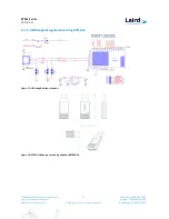
. For more information on how to integrate the USB interface
on BT85xd, see
Figure 15
located in the following section:
USB Dongle Design Example Using BT850
.
The following USB interface features are supported:
USB Protocol, revision 2.0, full-speed compliant with LPM support (up to 12 Mbps)
Bluetooth HCI
HID, DFU, UHE (proprietary method to emulate an HID device at system boot)
Integrated detach resistor
USB termination when interface is not in use
Internal modules, certification, and non-specification compliant operation
8.3.
PCM Interface
The BT850-Sx supports two independent PCM interfaces that share the pins with I
2
S interfaces. The PCM
interface on the BT850-Sx can connect to linear PCM Codec devices in master or slave mode. In master mode,
the BT850-Sx generates the PCM_CLK and PCM_SYNC signals; in slave mode, these signals are provided by
another master on the PCM interface and are inputs to the BT850-Sx.
The configuration of the PCM interface may be adjusted by the host through the use of vendor-specific HCI
commands.
8.3.1.
Slot Mapping
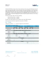
The BT850-Sx supports up to three simultaneous full-duplex SCO or eSCO channels through the PCM interface.
These three channels are time-multiplexed onto the single PCM interface by using a time-slotting scheme where
the 8 kHz or 16 kHz audio sample interval is divided into as many as 16 slots. The number of slots is dependent
on the selected interface rate of 128 kHz, 512 kHz, or 1024 kHz. The corresponding number of slots for these
interface rate is 1, 2, 4, 8, and 16, respectively. Transmit and receive PCM data from an SCO channel is always
mapped to the same slot. The PCM data output driver tristates its output on unused slots to allow other devices
to share the same PCM interface signals. The data output driver tristates its output after the falling edge of the
PCM clock during the last bit of the slot.
8.3.2.
Frame Synchronization
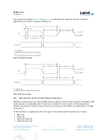
The BT850-Sx supports both short- and long-frame synchronization in both master and slave modes. In short-
frame synchronization mode, the frame synchronization signals an active-high pulse at the audio frame rate that
is a single-bit period in width and is synchronized to the rising edge of the bit clock. The PCM slave looks for a
high on the falling edge of the bit clock and expects the first bit of the first slot to start at the next rising edge of
the clock.
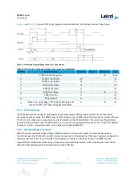
Figure 2
and
Table 9
shows PCM Timing Diagram and Specifications for the master mode of short-frame.


