BT85x Series
Datasheet
Embedded Wireless Solutions Support Center:
http://ews-support.lairdtech.com
www.lairdtech.com/bluetooth
12
© Copyright 2017 Laird. All Rights Reserved
Americas: +1-800-492-2320
Europe: +44-1628-858-940
Hong Kong: +852 2923 0610
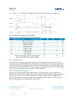
Ref No.
Characteristics
Minimum
Typical
Maximum
Unit
3
PCM bit clock HIGH
41
-
-
ns
4
PCM_SYNC setup
8
-
-
ns
5
PCM_SYNC_hold
8
-
-
ns
6
PCM_OUT delay
0
-
25
ns
7
PCM_IN setup
8
-
-
ns
8
PCM_IN hold
8
-
-
ns
9
Delay from rising edge of PCM_BCLK during last bit
period to PCM_OUT becoming high impedance
0
-
25
ns
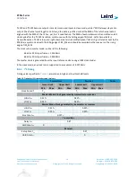
In long-frame synchronization mode, the frame synchronization signal is again an active-high pulse at the audio
frame rate; however, the duration is three bit periods and the pulse starts coincident with the first bit of the first
slot.
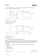
Figure 4
and
Table 11
shows PCM Timing Diagram and Specifications for the master mode of long-frame.
Figure 4: PCM timing diagram (Long-Frame Sync, Master Mode)
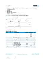
Table 11: PCM Interface timing specifications (Long-Frame Sync, Master Mode)
Ref No.
Characteristics
Minimum
Typical
Maximum
Unit
1
PCM bit clock frequency
-
-
12
MHz
2
PCM bit clock LOW
41
-
-
ns
3
PCM bit clock HIGH
41
-
-
ns
4
PCM_SYNC delay
0
-
25
ns
5
PCM_OUT delay
0
-
25
ns
6
PCM_IN setup
8
-
-
ns
7
PCM_IN hold
8
-
-
ns
8
Delay from rising edge of PCM_BCLK during last bit
period to PCM_OUT becoming high impedance
0
-
25
ns


