75
www.lairdtech.com
Laird Technologies
BTM510/511
Bluetooth
®
Multimedia Module
2. Codec Gain
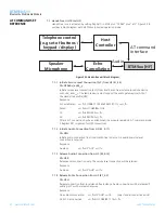
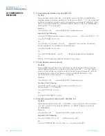
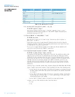
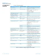
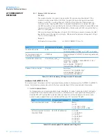
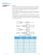
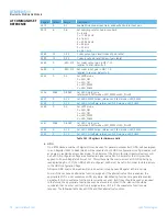
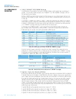
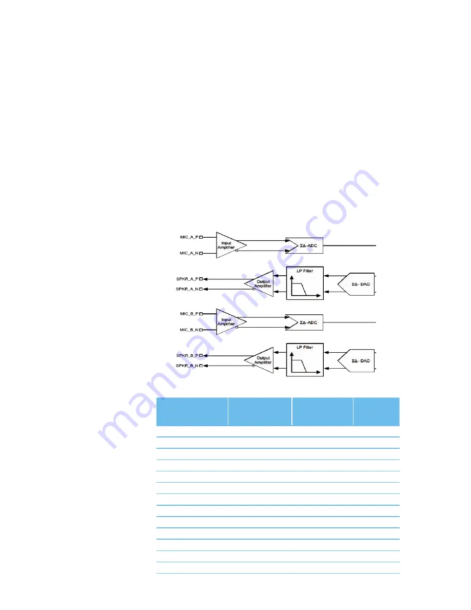
Analogue input and output gains (Input Amplifier, Output Amplifier, Figure 3.25) can be set to one
of 23 steps called “Gain Level”. To each gain level, an overall gain (dBr) is assigned, according to
Table 3.34. The overall gain is formed by an analogue and a digital component as outlined in Table
3.34. Gain values can be specified either as gain level or as overall gain by separate S Registers.
Please note that a pair of such S-Registers always updates the other corresponding S-Register
(e.g., S589 – S689 and S590 – S690).
For S689 and S690, the overall gain (dBr) must be entered multiplied by 10. If the input value doesn’t
match a gain table entry, the nearest possible value is set. The actually set value can be checked by
reading back S689/S690. The value of S689/S690 is printed out multiplied by 10 in order to avoid
non integer numbers.
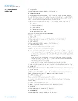
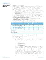
The command class “AT+G…” enables incremental and decremental gain settings. The increment/
decrement command corresponds to one row up/down in the gain table (Table 3.34). The Gain level
registers S589/S689 and S590/S690 are not affected by increment/decrement commands. Instead,
the current gain level is cached and can be retrieved by “AT+G(I|O)?”. There are two further commands
to restore the cached gain level from S589/S590 (“AT+G(I|O)R”) and to save the currently cached gain
level to S589/S590 (“AT+G(I|O)S”).
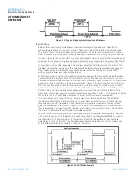
Figure 3.27: Stereo Audio Codec Block Diagram
Output Gain Level or
Input Gain Level
S589 or S590
Overall Gain (dBr)
S689 or S690
Digital
Component
Analogue
Component
22
+21.5
7
7
21
+18.0
6
7
20
+15.5
5
7
19
+12.0
4
7
18
+9.5
3
7
17
+6.0
2
7
16
+3.5
1
7
15
0
0
7
14
-3.0
0
6
13
-6.0
0
5
12
-9.0
0
4
11
-12.0
0
3
10
-15.0
0
2
AT COMMAND SET
REFERENCE

