8
www.lairdtech.com
Laird Technologies
BTM510/511
Bluetooth
®
Multimedia Module
NOTES FOR PCB LAYOUT:
1.
The RF output pin must be matched to a 50
Ω
strip-line or coplanar waveguide on the antenna-less version (BTM510).
2.
Ensure that there are no exposed conductors under the module to avoid shorts to the test points on the module underside.
3.
The PCB footprint is provided for guidance only. Users may wish to modify the PCB land dimensions to suit their specific
manufacturing or process.
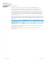
OPERATINg PARAMETERS
RECOMMENDED OPERATING CONDITIONS
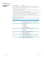
Operating Condition
Min
Max
VDD_USB
(USB compatibility not required)
1.7
3.6
VDD_USB
(USB compatibility required)
3.1
3.6
VDD_IO
1.7
3.3
VDD_IN
3.0
3.6
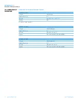
VOLTAgE SPECIFICATIONS
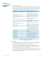
LOGIC LEVELS (VUSB)
Input Voltage Levels
Min
Typ
Max
V
ih
0.625VDD_USB
0.3
V
il
-0.3
0.25VDD_USB
Output Voltage Levels
V
oh
(Iout = -4mA)
0.75VDD_USB
VDD_USB
V
ol
(Iout = 4mA)
0
0.125
LOGIC LEVELS (VIO)
Input Voltage Levels
Min
Typ
Max
V
ih
0.625VDD_IO
0.3
V
il
-0.3
0.25VDD_IO
Output Voltage Levels
V
oh
(Iout = -4mA)
0.75VDD_IO
VDD_IO
V
ol
(Iout = 4mA)
0
0.125
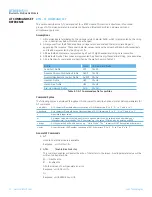
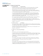
LOGIC LEVELS (VUSB – USB TERMINALS D+, D-)
Input Voltage Levels
Min
Typ
Max
V
ih
0.7VDD_USB
V
il
0.3VDD_USB
Output Voltage Levels (to correctly terminated USB cable)
V
oh
2.8
VDD_USB
V
ol
0
0.2
OPERATINg
PARAMETERS


