20
www.lairdtech.com
Laird Technologies
BTM520/521
Bluetooth
®
Multimedia Plus Module
CONFIGURING
THE BTM520/521
REGISTER
DEFAULT
RANGE
COMMENT
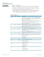
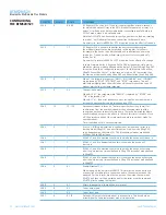
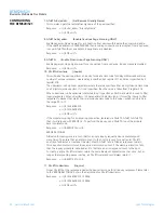
S551
0x3211
0xFFFF
This register specifies in each 4 bit nibble, how the outgoing modem status
bits to the remote peer gets its value. Bluetooth
®
allows for RTR, RTC, DV
and IC bits to be exchanged over an RFCOMM connection.
Nibble 0..3 specifies the source for RTC
4..7 specifies the source for RTR
8..11 specifies the source for DV (i.e. DCD)
12..15 specifies the source for IC (i.e. RI)
Each nibble can take the following value:-
0 Always set to 0
1 Always set to 1
2 If DCD (pin 8 on module connector) is output then always 1
If DCD is input then 1 if DCD is asserted otherwise 0
3 If RI (pin 6) is output then always 0
If RI is input then 1 if RI is asserted otherwise 0
4 If DSR (pin 10) is asserted then 1 otherwise 0
In the event that a nibble specifies DSR as the source of its state, be aware
that if, S Register 507 is anything other than 0, a de-assertion of DSR will
cause the Bluetooth connection to be dropped.
If bits 0..3 and 4..7 are set to 0, then some Bluetooth devices will use
that as a signal to stop sending any data back. For example, Nokia 6310
stops responding.
If this register is changed while in command and connected mode, then
on going back online using the ATO command, a fresh signal will be sent
to the peer to update the bits.
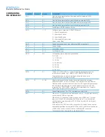
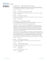
S552
0x0122
0x0FFF
This register specifies in each 4 bit nibble, how the DTR, DCD, RI output
pins are controlled when in a Bluetooth connection
Nibble 0..3 specifies the source for DTR
4..7 specifies the source for DCD
8..11 specifies the source for RI
Each nibble can take the following value:-
0 Do NOT touch the I/O
1 Always deassert
2 Always assert
3 If RTC bit in CONTROL_IND is 1 then assert otherwise deassert
4 If RTR bit in CONTROL_IND is 1 then assert otherwise deassert
5 If DV bit in CONTROL_IND is 1 then assert otherwise deassert
6 If IC bit in CONTROL_IND is 1 then assert otherwise deassert
If this register is changed while in command and connected mode, then
on going back online using the ATO command, the modem output lines
will get refreshed.
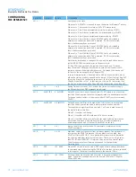
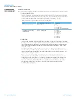
S553
0x0201
0x0FFF
This register specifies in each 4 bit nibble, how the DTR,DCD,RI output pins
are controlled when NOT in a Bluetooth connection
Nibble 0..3 specifies the source for DTR
4..7 specifies the source for DCD
8..11 specifies the source for RI
In addition it also refers to S Register 552 to see if the relevant pin is an
input or not to be touched. If the nibble in 552 is 0, then the relevant pin
is an input.
Each nibble can take the following value:-
0 Always deassert
1 Always assert
2 Assert if RING is being sent to the host

