18
www.lairdtech.com
Laird Technologies
BTM520/521
Bluetooth
®
Multimedia Plus Module
CONFIGURING
THE BTM520/521
REGISTER
DEFAULT
RANGE
COMMENT
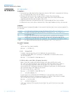
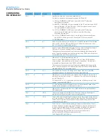
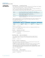
S512
1
0..7
Specify power up state.
When set to 0, AT+BTO is required to open the device for Bluetooth
®
activity.
When set to 1, it proceeds to a state as if AT+BTO was entered.
When set to 2, it will be discoverable only, similar to issuing AT+BTQ.
When set to 3, it will be connectable but not discoverable e.g. AT+BTG
When set to 4, it will be connectable and discoverable e.g. AT+BTP.
When set to 5, it will be like 2, but all UART RX traffic is discarded in
absence of a connection while DSR is asserted. If DSR is not asserted,
then it behaves exactly as per mode 2.
When set to 6, it will be like 3, but all UART RX traffic is discarded in
absence of a connection while DSR is asserted. If DSR is not asserted,
then it behaves exactly as per mode 3.
When set to 7, it will be like 4, but all UART RX traffic is discarded in
absence of a connection while DSR is asserted. If DSR is not asserted,
then it behaves exactly as per mode 4.
Note that by implication, a change to this can only be seen after a power
cycle AND if AT&W is actioned prior to the power cycle.
If S Reg 554 is non-zero and this register is between 2 and 7 inclusive,
then the value of S554 specifies the time in seconds that the device will
remain in the specified mode after power up. On timeout, the device will
fall back to the mode specified in S Register 555.
In some firmware builds, S Registers 565 to 569 inclusive are visible, which
allows the start-up mode to depend on the state of RI line (Setting S Reg 565
forces the RI pin to be configured as an input). For this feature to be active,
SReg 565 should be set to 1. In that case, on start-up, if RI is asserted, then
the start-up mode is defined by S Reg 566 and if deasserted then S Reg 567.
S514
10
1..60
Pairing Timeout in seconds. This includes the time a host takes to supply
the PIN number when PIN? messages are indicated.
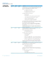
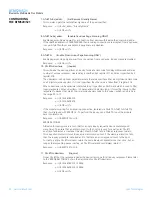
S515
0x001F00
0.. 0xFFFFFF
Default Device Class Code to be used with AT+BTO when it is not explicitly
specified. When queried, the value is always printed as a hexadecimal number.
To change the device class of the module, after AT+BTO, use the command
AT+BTC.
S516
0x000000
0..0x2FFFFFF
Default Device Class filter to be used with AT+BTI when it is not explicitly
specified. When queried the value is always printed as a hex number.
The seventh most significant digit, can be 0,1 or 2, and is used to specify
the type of device class filter.
When 0, it specifies no filtering.
When 1, it specifies an AND mask and all 24 bits are relevant
When 2, it specifies a filter to look for devices with matching major device
class which occupies a 5 bit field from bits 8 to 12 inclusive (assuming
numbering starts at bit 0). All other 19 bits MUST be set to 0.
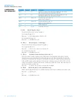
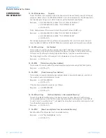
S517
20
2..61
Inquiry Length in units of seconds. This parameter is referenced by the
AT+BTI command.
S518
8
0..255
Maximum number of responses from an inquiry request. This parameter is
reference by the AT+BTI command. If this number is set too high, then
AT+BTI will return ERROR 27. For a particular firmware revision, determine
the effective maximum value by trial and error. That is, set to a high value,
send AT+BTI and if ERROR 27 is returned, then retry with a smaller value.
This effective max value will remain unchanged for that particular
firmware build.
S519
500
100..6000
When S507>0, and in a connection, DSR can be used to change from data
to command state by deasserting the DSR line for less than the time specified
in this register. This value is rounded down to the nearest 100ms
S530
1000
100..15000
Reconnect delay when configured as master in pure-cable-replacement
mode. This value is rounded down to the nearest 100ms. See S Register
505 and 543 also.


