Please read all instructions carefully before attempting to
install and use this product.
SAFETY
The CMX69273P and all associated equipment should be installed in
accordance with all applicable local and national electrical code
guidelines to ensure safe operation.
SPECIFICATIONS – Model Number
CMX69273P
Frequency
698 MHz - 960MHz
1710MHz - 2700 MHz
Gain (dBi)
4.
1
(typical), 4.
5
(max) @ 700 Band
4.2 (typical), 4.
2
(max) @ 800 Band
4.1 (typical), 4.
2
(max) @ 900 Band
3.3 (typical),
3.
5
(max) @ 1800 Band
2.9 (typical), 3.
3
(max) @ 1900 Band
2.6 (typical),
2
.
9
(max) @ 2100 Band
2.8 (typical),
3
.
3
(max) @ 2300 Band
3.1 (typical), 3.
3
(max) @ 2600 Band
Port to Port Isolation
<-1
6
dB
@
698-960MHz
<-1
6
dB @ 1710-2700MHz
PIM, 3rd order, 2X20W
< -150dBc
Nominal Impedance
50 Ohms
Polarization
Linear, Omnidirectional
VSWR
1
.
7
:1 max across the bands
Power Input (Max.)
50 Watts (ambient temp of 25
°
C)
Operating Temperature
Range
-
4
0°C +
85
°C
Cable
Semi flexible 402 cable
Connector
Model Specific
Exposed Cable length, Lc
Model Specific
Weight
Approximately 0.60 kg
(1.32 lbs.)
Mounting
Ceiling
mount (drywall or tile flush mount)
Radome
PC/ABS, UL94 V-0 (White)
Dimensions, mm
Ø250mm (W) x 49mm (H)
RoHs
Compliant
CMX69273P
698‐2700MHz Ceiling Mount
Antenna
ASSEMBLY AND INSTALLATION INSTRUCTIONS
1
65-00152_A
C
_1
215
14
PRECAUTION
For best PIM results:
1. Make sure the connectors are clean and free from any metal
flakes/dirt & tighten the connectors using torque wrench
according to connector torque specification below.
2. Avoid extreme bending to the cable.
3. During installation of the antenna, both cables should not be
crossing one another.
4. Do not remove the dust cap from connectors when not in use.
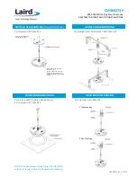
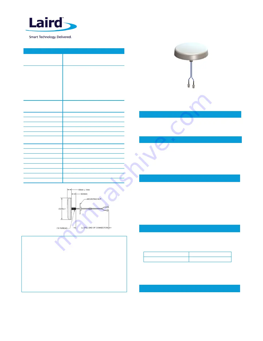
A threaded post on the back of the antenna and a supplied
mounting nut are the primary mounting method when access is
available to both sides of the mounting surface, such as a
suspended ceiling tile. Mark the desired mounting location on the
tile and cut a ø40mm (1.57”) hole for threaded post. Feed the
cables through the hole and secure the antenna with the mounting
nut. (See figure 1).
The CM
X
6927
3
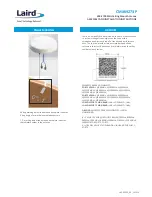
P antenna is designed and optimized for LTE MIMO
system requirements covering a wide range of operating frequency.
The covered frequency range includes the band of 700/ 850/ 900/
1800/ 1900/2
1
00/
2300/
2
6
00. The antenna offers low cross
correlation between the two radiating elements suitable for MIMO
applications.
APPLICATION
Warranty and Liability
Laird warrants to the original purchaser that antenna products will remain free from
defects in materials and workmanship for a period of five (5) years from the purchase
date. If any such defect is discovered within the warranty period, Laird will at its sole
option, repair or replace the Product free of charge upon its return to the factory. This
warranty applies only if the Product is used in a normal fashion, and is void if the
Product is abused, disassembled, tampered with, used unreasonably, or fails as a
result of normal wear. Furthermore, this warranty applies only to defects, which occur
where the proper Product is selected as recommended by Laird and is used in the
fashion recommended by Laird for the defective Product. THIS WARRANTY IS IN LIEU
OF ALL OTHER WARRANTIES, EXPRESSED OR IMPLIED, AND S LIMITED TO A PERIOD OF
FIVE (5) YEARS FROM THE DATE OF ORIGINAL PURCHASE. LAIRD IS NOT LIABLE FOR
INCIDENTAL OR CONSEQUENTIAL DAMAGES OF ANY KIND. ANY WARRANTY EXTENDED
HEREIN SHALL BE LIMITED TO THE PRICE PAID TO LAIRD FOR THE DEFECTIVE
PRODUCT. WHERE STATE OR LOCAL LAW GOVERNS THE PERIOD OF WARRANTY, SUCH
PERIOD SHALL CONTROL.
Americas: +1.847 839.6907
IAS-AmericasEastSales@lairdtech.com
Europe: +44.1628.858941
IAS-EUSales@lairdtech.com
Asia; +86.21.5855.0827.127
IAS-AsiaSales@lairdtech.com
www.lairdtech.com
For best results, mount the antenna near the center of the coverage
area. A line-of-sight path between the antenna and active floor
locations generally works best. Although microwave signals
penetrate cubical dividers and interior walls with little attenuation,
reinforced block walls, banks of metal cabinets, or steel shelving may
attenuate signals or cause multipath, a condition where reflected
signals interfere with the primary signal path. Avoid mounting next to
a column or vertical support that could create a “shadow zone” of
reduced coverage to one portion of the room.
LOCATION
Mini-Din 4.1-9.5
N-Type
90 inch/LBS (10.16Nm)
25 inch/LBS (2.82Nm)
STANDARD MOUNTING
Figure 1
Patent Pending


