Sterling-LWB(5) SD Card Board
User Guide
Embedded Wireless Solutions Support
Center: http://ews-support.lairdtech.com
www.lairdtech.com/wireless
330-0245-R1.1
6
© Copyright 2017 Laird. All Rights Reserved
Americas: +1-800-492-2320
Europe: +44-1628-858-940
Hong Kong: +852 2923 0610
3
S
TERLING
-LWB
(5)
SD
C
ARD
B
OARD
H
ARDWARE
See the LSR website for the full PCB, schematic, and BOM of the Sterling-LWB & Sterling-LWB5 SD card board:
Sterling-LWB
https://www.lsr.com/embedded-wireless-modules/wifi-plus-bluetooth-module/sterling-lwb
Sterling-LWB5
https://www.lsr.com/embedded-wireless-modules/wifi-plus-bluetooth-module/sterling-lwb5
3.1.
Interface Connectors
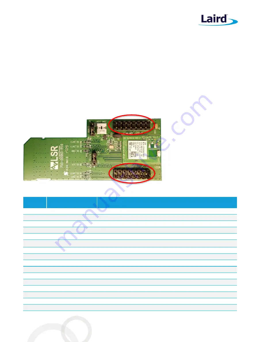
The Laird Sterling-LWB and Sterling-LWB5 SD card board has two connectors (J2 and J3) for interfacing with the
host development board. This provides all necessary pins to completely connect the module to the host for both
Wi-Fi and Bluetooth operation.
Figure 5: Sterling-LWB SD card board connectors
Table 1: Connector J2 pinout
J2 Pin
Number
Pin Name
Description
1
VIN_3V3
3.3V Input Voltage
2
WIFI_GPIO_1
Wi-Fi GPIO 1 from the module
3
WL_HOST_WAKE
Wi-Fi host wake signal
4
WIFI_GPIO_2
Wi-Fi GPIO 2 from the module
5
NC
No Connect
6
WIFI_GPIO_3
Wi-Fi GPIO 3 from the module
7
NC
No Connect
8
BT_GPIO_5
Bluetooth GPIO 5 from the module
9
EXT_32KHZ_CLK
32KHz Clock
10
WIFI_GPIO_4
Wi-Fi GPIO 4 from the module
11
CLK_REQ
Wi-Fi SDIO clock request
12
NC
No Connect
13
NC
No Connect
14
NC
No Connect
15
NC
No Connect
16
GND
Ground


