background image

Doc#: 60-70-004 
Revision: 07 


Page 9


User’s Manual 


USA: +1 888.246.9050 Europe: +44.1342.315044 Asia: +886.3.312.9292 

www.lairdtech.com 

 clv.customerpos@lairdtech.com 


6.


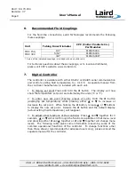
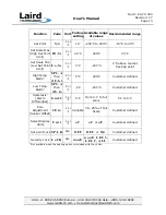
Recommended Fluid Couplings 


For the fluid line connections, Laird Technologies recommends the following 
male couplings. 


Unit 

Tubing Inner Diameter 

CPC (Colder Products Co.)     

Part Number 

  1/4” 


PLCD26004 

5/16” 


PLCD26005 

MRC 150,  

MRC 300 

 3/8” 


PLCD26006* 

* A pair of the indicated couplings is included with each chiller unit. 


For technical questions about these couplings, or to locate a distributor, 

please visit CPC’s website, www.colder.com. 


7.


Digital Controller 


The controller is available with either RS232 or RS485 serial communication 
and controls exiting fluid temperature to 

±

 0.16

°

C.  A separate manual from 

the controller manufacturer is included with each unit. 


1.


To display set point Press and hold the 

»

 button.  The display will now 

show the temperature set point and alternately the units (

°

C or 

°

F). 


2.


To enter new set point (Factory preset at 10

°

C) Hold the 

»

 button 

(displaying set temperature) while pressing either 

f

 or 

g

 to increase or 

decrease the set point.  While holding the 

»

 button, release 

f

 or 

g

 buttons 

to display the new set point.  Release the 

»

 button and the default display 

(actual exiting fluid temperature) will reappear. 


3.


To adjust other functions of the controller  Press 

f

 and 

g

 together for 3 

seconds.  

f

 or 

g

 will scroll through the functions available on that menu level 

and pressing either 

»

 and 

f

 together or 

»

 and 

g

 together will change menu 

levels.  The following table gives some information concerning some of the 
common operational functions of the controller.  To change functions other 

than those shown (recommended for advanced users only), please consult the 
separate manual for the controller. 


Summary of Contents for MRC 150

Page 1: ...004 Revision 07 MRC 150 300 Thermoelectric Re circulating Liquid Chiller User s Manual USA 1 888 246 9050 Europe 44 1342 315044 Asia 886 3 312 9292 Website www lairdtech com Email clv customerpos lair...

Page 2: ...the cooled product This manual provides the necessary general information for proper installation and operation and has been developed to achieve the best results when using the Laird Technologies ch...

Page 3: ...REPLACED BY A CORD WITH AN EQUAL OR HIGHER RATING Failure to follow the above precautions could result in electrical shock fire personal injury or damage to the unit and will void the warranty 4 Techn...

Page 4: ...19 5 35 1 12 0 7 7 13 8 39 1 20 3 33 8 15 4 8 0 13 3 Weight kg lbs 10 9 24 13 6 30 Maximum flow rate LPM GPM 4 2 9 0 76 3 3 0 87 3 Capacity rating is given at a temperature of 25 C 77 F for the ambie...

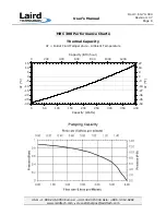
Page 5: ...86 3 312 9292 www lairdtech com clv customerpos lairdtech com MRC 150 Performance Charts Therma T Outlet Fluid Temperat 30 25 20 15 10 5 0 5 10 15 0 50 Capac T C 100 200 300 400 500 600 Capacity BTU h...

Page 6: ...2 9292 www lairdtech com clv customerpos lairdtech com MRC 300 Performance Charts Thermal Capacity T Outlet Fluid Temperature Ambient Temperature 30 25 20 15 10 5 0 5 10 15 0 50 100 150 200 250 300 35...

Page 7: ...Doc 60 70 004 Revision 07 Page 7 User s Manual USA 1 888 246 9050 Europe 44 1342 315044 Asia 886 3 312 9292 www lairdtech com clv customerpos lairdtech com...

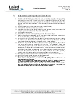
Page 8: ...culating in the reservoir otherwise turn off the chiller and wait another 5 minutes See Note Below 9 If there is any doubt that the system has been purged of air then check the fluid level and fill re...

Page 9: ...acturer is included with each unit 1 To display set point Press and hold the button The display will now show the temperature set point and alternately the units C or F 2 To enter new set point Factor...

Page 10: ...coolant freezing point High Temp Alarm1 S P 2 A then d U h i C or F 5 C 400 C Customer defined Low Temp Alarm1 S P 2 A then d U l o C or F 1 C 200 C Customer defined Hysteresis1 Alarm Differential b n...

Page 11: ...roperly 3 Consult Factory Unit is running but the Low Fluid Indicator LED is lit Insufficient fluid level in reservoir Fill up reservoir following air purge instructions Section 5 of this manual Unit...

Page 12: ...ct to Laird Technologies freight prepaid Laird Technologies in turn will return the warranted product to customer freight prepaid if within the time period specified above Warranty coverage is in effe...

Page 13: ...s for a particular purpose Laird Technologies will in no way be liable for incidental or consequential damage whatsoever or for any other claims by the customer for damages in connection with Laird Te...

Reviews: