background image


Laird MSD45N 

Hardware Integration Guide 
Version 1.1 


Embedded Wireless Solutions Support Center: 

http://ews-support.lairdtech.com


Americas: +1-800-492-2320 Option 2 
Europe: +44-1628-858-940 
Asia: +852-2923-0610 

www.lairdtech.com/wireless 


Summary of Contents for MSD45N

Page 1: ...Hardware Integration Guide Version 1 1 Embedded Wireless Solutions Support Center http ews support lairdtech com Americas 1 800 492 2320 Option 2 Europe 44 1628 858 940 Asia 852 2923 0610 www lairdtech com wireless ...

Page 2: ...tech com www lairdtech com wireless 2 Laird Technologies Americas 1 800 492 2320 Option 2 Europe 44 1628 858 940 Hong Kong 852 2268 6567 x026 REVISION HISTORY Version Revision Date Change Description 1 0 25 July 2014 Initial Release 1 1 5 August 2014 Added note to SDIO Timing Requirements regarding SDIO bus clock rate ...

Page 3: ...scription 4 Block Diagram 5 Specifications 5 Recommended Operating Conditions and DC Electrical Characteristics 8 SDIO Timing Requirements 9 Pin Definitions 10 MSD40NBT and MSD45N Pin Comparison Table 13 Integration Considerations 14 Mechanical Specifications 15 Connector Overview 15 MSD45N Attached to T Board 15 Mounting 16 RF Layout Design Guidelines 16 Regulatory 17 Certified Antennas 17 Docume...

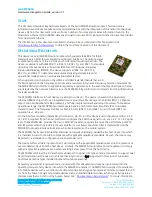
Page 4: ...roviding a Media Access Controller MAC a Physical Layer Controller baseband or BB processor and fully integrated dual band radio transceiver To maximize operational range the MSD45N incorporates external 2 4 and 5 GHz power amplifiers PA to increase transmit power The frequency stability for both 2 4 GHz 802 11b and 802 11g and 5 GHz 802 11a operation is 20 ppm On the interface connector Molex 60 ...

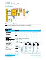
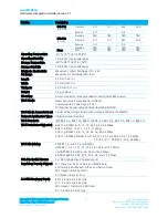
Page 5: ...i Fi Interface 1 bit or 4 bit Secure Digital I O Note Can support 1 8 V or 3 3 V depending on the supply voltage on VDDIO pin 21 Antenna Interface 1 Hirose U FL connector Main Chip Qualcomm Atheros AR6003 single chip client Input Voltage Requirements 3 3 VDC 5 core I O Signalling Voltage 3 3 VDC 5 1 8 VDC 5 Average Current Consumption At maximum transmit power setting Note Standby refers to the ra...

Page 6: ...ect Sequence Spread Spectrum DSSS Complementary Code Keying CCK Orthogonal Frequency Divisional Multiplexing OFDM Wi Fi Media Access Protocol Carrier sense multiple access with collision avoidance CSMA CA Network Architecture Types Infrastructure and ad hoc Wi Fi Standards IEEE 802 11a 802 11b 802 11d 802 11e 802 11g 802 11h 802 11i 802 11n Wi Fi Data Rates Supported 802 11a OFDM 6 9 12 18 24 36 4...

Page 7: ...stream and 20 MHz wide channels for N rates 802 11a 6 Mbps 15 dBm 32 mW 54 Mbps 15 dBm 32 mW 802 11b 1 Mbps 16 dBm 40 mW 11 Mbps 16 dBm 40 mW 802 11g 6 Mbps 16 dBm 40 mW 54 Mbps 14 dBm 25 mW 802 11n 2 4 GHz 6 5 Mbps MCS0 16 dBm 40 mW 65 Mbps MCS7 12 dBm 16 mW 802 11n 5 GHz 6 5 Mbps MCS0 15 dBm 32 mW 65 Mbps MCS7 12 dBm 16 mW Typical Receiver Sensitivity Note All values nominal 3 dBm 802 11a 6 Mbps...

Page 8: ...rtifications are pending Wi Fi Alliance 802 11a 802 11b 802 11g 802 11n WPA Enterprise WPA2 Enterprise Cisco Compatible Extensions Version 4 Warranty Limited Lifetime All specifications are subject to change without notice RECOMMENDED OPERATING CONDITIONS AND DC ELECTRICAL CHARACTERISTICS Table 2 Absolute Maximum Ratings Symbol Parameter Min Typ Max Unit VCC3_3 Power supply voltage with respect to...

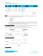
Page 9: ...ault mode timing Note The SDIO bus should not exceed a 25 MHz clock rate Figure 2 SDIO Default Mode Timing Note Timing is based on CL 40 pF load on CMD and Data Table 4 SDIO Timing Requirements Symbol Parameter Min Typ Max Unit fPP Frequency Data Transfer mode 0 50 MHz tWL Clock low time 7 ns tWH Clock high time 7 ns tTLH Clock rise time 10 ns tTHL Clock low time 10 ns Inputs CMD DAT referenced to...

Page 10: ...ct No internal connection Leave it open Leave open 12 No Connect No internal connection Leave it open Leave open 13 VCC3_3 3 3 V Module Power 14 No Connect No internal connection Leave it open Leave open 15 No Connect No internal connection Leave it open Leave open 16 No Connect No internal connection Leave it open Leave open 17 No Connect No internal connection Leave it open Leave open 18 No Conn...

Page 11: ... Leave it open Leave open 41 No Connect No internal connection Leave it open Leave open 42 WL_LED_ACT ANTE O LOW VCC3_3 Used for the following Antenna switch control signal when sharing antenna with BT signal See Sharing Antenna Implementation for more information LED indicator for Wi Fi is active sending a signal 43 No Connect No internal connection Leave it open Leave open 44 No Connect No inter...

Page 12: ... the following lines are available on the radio you are integrating into your system you must connect and control them with the host device CHIP_PWD_L SYS_RST_L BT_RST_L VDDIO_DR If the radio stays powered up and the host goes down or is reset communications cannot be re established with the radio The host SDIO controller must re establish communication with the radio by reloading the radio firmwa...

Page 13: ...t No Connect 10 BT_PCM_OUT No Connect 40 No Connect No Connect 11 BT_UART_CTS_N No Connect 41 No Connect No Connect 12 BT_WAKE_B No Connect 42 RSVD WL_LED_ACT ANTE 13 VCC3_3 VCC3_3 43 No Connect No Connect 14 No Connect No Connect 44 No Connect No Connect 15 No Connect No Connect 45 No Connect No Connect 16 No Connect No Connect 46 No Connect No Connect 17 No Connect No Connect 47 No Connect No Co...

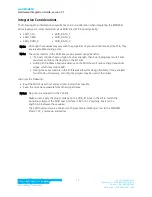
Page 14: ... of your host interface and the PCB they are a reasonable starting point Note The series resistors in the SDIO bus provide several design benefits If a host controller has too high of a drive strength then bus ringing may result Series resistors can reduce this ringing on the I O lines Adding 27 56 ohms of series resistance on the SDIO bus will reduce sharp transitional edges which may reduce EMI ...

Page 15: ...echnologies Americas 1 800 492 2320 Option 2 Europe 44 1628 858 940 Hong Kong 852 2268 6567 x026 MECHANICAL SPECIFICATIONS Connector Overview MSD45N connector Molex 54722 0607 60 pin connector Mating connector on board Molex 55560 0607 60 pin connector Figure 5 Mechanical Drawing MSD45N Attached to T Board Figure 6 MSD45N attached to T board Units are millimeters ...

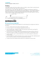
Page 16: ...ttached to the host Figure 7 Mounting Recommendations RF LAYOUT DESIGN GUIDELINES The following is a list of RF layout design guidelines and recommendation when installing a Laird radio into your device Do not run antenna cables directly above or directly below the radio Do not place any parts or run any high speed digital lines below the radio If there are other radios or transmitters located on ...

Page 17: ...r of the MSD45N to account for higher antenna gain In some cases OEMs may be able to reduce certification efforts by using antennas that are of like type and equal or lesser gain to the above listed antennas Documentation Requirements In order to maintain regulatory compliance when integrating the Laird MSD45N into a host device and leveraging Laird s grants and certifications it is necessary to m...

Page 18: ...ifications not expressly approved by the party responsible for compliance could void the user s authority to operate this equipment This device complies with Part 15 of the FCC Rules Operation is subject to the following two conditions 1 This device may not cause harmful interference and 2 this device must accept any interference received including interference that may cause undesired operation T...

Page 19: ...SD45N on the host product in such a location that it can be seen by an operator at the time of purchase User s Guide Requirements for Model MSD45N RF Radiation Hazard Warning To ensure compliance with FCC and Industry Canada RF exposure requirements this device must be installed in a location where the antennas of the device will have a minimum distance of at least 20 cm from all persons Using hig...

Page 20: ...ires requis pour ce module installé IMPORTANT NOTE In the event that these conditions cannot be met for example certain laptop configurations or co location with another transmitter then the Canada authorization is no longer considered valid and the IC ID can not be used on the final product In these circumstances the OEM integrator will be responsible for re evaluating the end product including t...

Page 21: ...al equipment related to human exposure restrictions for electromagnetic fields 0 Hz 300 GHz EN 300 328 V1 8 1 2012 06 Electromagnetic compatibility and Radio spectrum Matters ERM Wideband transmission systems Data transmission equipment operating using wide band modulation techniques Harmonized EN covering the essential requirements of article 3 2 of the R TTE Directive EN 301 893 V1 7 1 2012 06 B...

Page 22: ... ΤΙΣ ΛΟΙΠΕΣ ΣΧΕΤΙΚΕΣ ΔΙΑΤΑΞΕΙΣ ΤΗΣ ΟΔΗΓΙΑΣ 1999 5 ΕΚ Français French Par la présente nom du fabricant déclare que l appareil type d appareil est conforme aux exigences essentielles et aux autres dispositions pertinentes de la directive 1999 5 CE Italiano Italian Con la presente nome del costruttore dichiara che questo tipo di apparecchio è conforme ai requisiti essenziali ed alle altre disposizion...

Page 23: ... spĺňazákladnépožiadavky a všetkypríslušnéustanoveniaSmernice 1999 5 ES Suomi Finnish Valmistaja manufacturer vakuuttaa täten että type of equipment laitteen tyyppimerkintä tyyppinen laite on direktiivin 1999 5 EY oleellisten vaatimusten ja sitä koskevien direktiivin muiden ehtojen mukainen Svenska Swedish Härmed intygar företag att denna utrustningstyp står I överensstämmelse med de väsentliga eg...

Page 24: ...ort Center http ews support lairdtech com www lairdtech com wireless 24 Laird Technologies Americas 1 800 492 2320 Option 2 Europe 44 1628 858 940 Hong Kong 852 2268 6567 x026 APPENDIX A SCHEMATIC The following MSD45N schematic may be used as a reference Figure 8 Laird MSD45N Schematic ...

Page 25: ...Mouser Electronics Authorized Distributor Click to View Pricing Inventory Delivery Lifecycle Information Laird Technologies WH MSD45N ...

Reviews: