RAMP DVK Guide
Version 4.0
Americas: +1-800-492-2320 Option 3
9
Laird Technologies
Europe: +44-1628-858-940
Hong Kong: +852 2923 0610
www.lairdtech.com/ramp
Interfacing the SDK Board to Other RS-232 Hardware
The development kit serial board is defined as DCE (Data Communications Equipment). DCE is wired to
interface directly with DTE (Data Terminal Equipment). Typically, DTE is defined as a PC and DCE is defined as
a peripheral. To interface DCE to other DCEs, or DTE to other DTEs, a null modem is required. The null
modem swaps pins to convert a DCE to a DTE and vice-versa. Normally, a null modem consists of a female
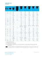
and a male DB9 connector. A typical null modem configuration is shown in
Table 6: DTE, DCE, and Null modem signal definitions
DCE
Pin #
DCE Signal
Name
DCE
Direction
DTE
Pin #
DTE Signal
Name
DTE
Direcion
Null Modem
Female DB9
Null Modem
Male DB9
1
DCD
O
1
DCD
I
1
4 or NC
2
TXD
O
2
RXD
I
2
3
3
RXD
I
3
TXD
O
3
2
4
DTR
I
4
DTR
O
4
6 and 1 or NC
5
GND
5
GND
5
5
6
DSR
O
6
DSR
I
6
4 or NC
7
RTS
I
7
RTS
O
7
8
8
CTS
O
8
CTS
I
8
7
9
RI
O
9
RI
I
9
NC
Interfacing the SDK Board to RS-485 Equipment
The SDK serial board has been designed to interface to RS-485 equipment. If such operation is desired, the
COMM Select jumper should be set to RS485 Enable. The RS-485 circuitry used by the SDK board has been
specially designed to negate the requirement for a DE/RE signal. Thus, the receiver is always enabled unless
the transceiver has something to send to the OEM host. The OEM must ensure that the OEM host does not
send data at the same time as the transceiver; otherwise a RS-485 contention occurs because the RS-485
hardware is half duplex.
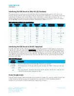
Table 7: RS-485 header pins
RS-485
Pin Name
Description
A TRUE
The non-inverted form of the serial data. This pin is at rest High.
B INVERT
The inverted form of the serial data (an exact inversion of A TRUE). This pin is at rest Low.
GND
GND
+5V
This is regulated 5V output from the serial board for general purpose use. A maximum of
100 mA should be drawn through this node.
Power Requirements
The serial board employs a National LM2940 linear regulator to regulate the incoming voltage to 5VDC. Due
to heat dissipation limitations and current requirements, a maximum of 10VDC should be present at
connector J4. A minimum of 5.5V should also be present at the connector.

