RAMP DVK Guide
Version 4.0
Americas: +1-800-492-2320 Option 3
5
Laird Technologies
Europe: +44-1628-858-940
Hong Kong: +852 2923 0610
www.lairdtech.com/ramp
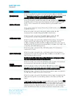
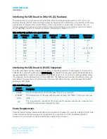
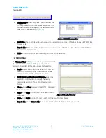
Table 1: Status LEDs
LED
Definition
+VCC
Lights when power is applied to the serial adapter board.
Low Power
Monitors the 5 volt supply and lights when the supply dips below 4.8 volts.
Reset
Lights when the Reset line to the processor is
High, resetting the transceiver.
TxD
Lights when the TXD line is
Low; flashes rapidly when data is transmitted from the
transceiver to the host.
RxD
Lights when the RXD line is
Low; flashes rapidly when data sent by the host is received by
the transceiver.
Forced 9600
Recovery
Lights when the 9600 Baud line is
Low; shows that the FORCED CONFIGURATION jumper
is set to force the transceiver to 9600 Baud. The transceiver must be reset before it is
forced to 9600.
Status 1
If used with a client transceiver, lights if the client transceiver is in range of a server
transceiver with the same system ID and channel number. If used with a server
transceiver, always lights when the server is powered in normal mode and is ready to
accept data.
Status 2
Reflects the state of the Command/Data pin (AC4490, AC4486, AC4424, AC4790,
AC4868), the TE pin (AC3124, AC1524) and the Pktmode pin (AC5124). This is
controlled by the PC RTS pin when the Program Mode/Normal Mode switch is set to
Program Mode. Lights when this pin goes Low.
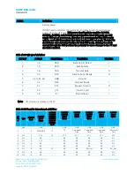
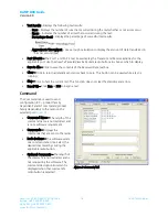
Table 2: LEDs – AC4490 only section (includes AC4486, AC4790, and AC4868)
LED
Definition
Potentiometer/AD In
This varies the voltage (0 – 3.3 V) presented to the AD In pin (pin 18).
Gen Out 0 LED
Lights when the GO0 pin (pin 1) is
Low.
Gen Out 1 LED
Lights when the GO1 pin (pin 9) is
Low.
Gen In 0 Pushbutton
When depressed, forces the GI0 pin (pin 4)
Low.
Gen In 1 Pushbutton
When depressed, forces the GI1 pin (pin 14)
Low.
DA_Out
Probe point that provides a location for measuring the DA_Out pin (pin 19).
GND
Probe point that provides a GND reference location.
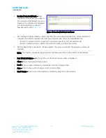
Table 3: Switch and jumper settings
Switch
Definition
Program Mode/
Normal Mode (S6)
When this switch is moved to the Program Mode position, the RTS pin from the
DB9/USB connector is connected to the Command/Data pin (AC4490,
AC4486, AC4424, AC4790, AC4868), the TE pin (AC3124, AC1524), and the
Pktmode pin (AC5124) of the transceiver. RTS of the transceiver is also
connected to GND. This allows the SDK software to control these pins with RTS
always enabled.
RESET (S1)
When this pushbutton is pressed, the transceiver hardware performs a soft
reset.


