RM024 User Manual
Version 2.3
Americas: +1-800-492-2320 Option 2
Europe: +44-1628-858-940
Hong Kong: +852-2923-0610
www.lairdtech.com/wireless
17
CONN-GUIDE-RAMP24-0413
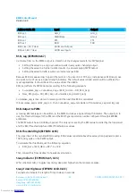
TXD Data Buffer and RTS
As data to be forwarded to the OEM Host accumulates, it is stored in the RM024’s outgoing buffer until the
radio is ready to begin sending the data to the OEM Host. Once the data packet has been sent to the Host
over the serial interface, it will be removed from the buffer and the radio will begin processing the next data
packet in the buffer. With RTS Mode disabled, the transceiver will send any data to the OEM Host as soon as
it has data to send. However, some OEM Hosts are not able to accept data from the transceiver all of the
time. With RTS Mode Enabled, the OEM Host can prevent the transceiver from sending it data by de-asserting
RTS (High), causing the transceiver to store the data in its buffer. Upon asserting RTS up to two additional
bytes can be received over the serial interface before the flow is stopped. Once RTS is re-asserted (Low), the
transceiver will continue sending data to the OEM Host, beginning with any data stored in its buffer.
Note: Leaving RTS de-asserted for too long can cause data loss once the radio’s TXD buffer reaches
capacity.
Tip:
Can I implement a design using just TXD, RXD, and GND (three-wire interface)?
Yes. However, it is strongly recommended that your hardware monitor the CTS pin of the radio. CTS is
taken High by the radio when its interface buffer is getting full. Your hardware should stop sending at
this point to avoid a buffer overrun (and subsequent loss of data). You can perform a successful design
without monitoring CTS. However, you need to take into account the amount of latency the radio adds
to the system, any additional latency caused by retries, how often you send data, non-delivery network
timeouts, and interface data rate. Laird Technologies can assist in determining whether CTS is required
for your application.
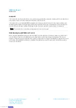
Radio Configurations
Antenna Switch (EEPROM 0xC1, bit 5)
Selects either integrated chip antenna or U.FL connector for external antenna
Note: On RM024 –C units with no integrated antenna, the RF switch is still active and it is possible,
though not advised to switch to the integrated antenna option, even though there is no antenna
connected. RF performance in this configuration would be degraded. See
Antenna Select Override
for additional options.
Antenna Select Override (EEPROM 0x5B)
Disables the antenna switch on –C products causing the firmware to ignore the setting in Antenna Switch
and use the U.FL port automatically.
Note: Product ID’s containing an “M” (RM024-S125-M-01, RM024-P125-M-01, RM024-S50-M-01 and
RM024-P50-M-01) have both antennas installed (chip antenna and u.FL). However, products
containing a “C” (RM024-S125-C-01, RM024-P125-C-01, RM024-S50-C-01 and RM024-P50-C-
01) only have the u.FL installed. Therefore, selecting chip antenna on a “C” product results in no
RF link. This feature does not work in FW v1.3-0 on 50 mW radios (RM024-x50-C-01).
Downloaded from
Downloaded from
Downloaded from
Downloaded from
Downloaded from
Downloaded from
Downloaded from
Downloaded from
Downloaded from
Downloaded from
Downloaded from
Downloaded from
Downloaded from
Downloaded from
Downloaded from
Downloaded from
Downloaded from


