RM024 User Manual
Version 2.3
Americas: +1-800-492-2320 Option 2
Europe: +44-1628-858-940
Hong Kong: +852-2923-0610
www.lairdtech.com/wireless
23
CONN-GUIDE-RAMP24-0413
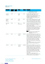
Address 0x68, Bit
Input
Output
Bit 2 set
GIO_7
GIO_3
Bit 3 set
CMD/Data
GIO_2
Bit 4 set
RTS
CTS
Bit 5 set
RXD
TXD
Bit 6 clear, Bit 7 clear
All I/O are Outputs
Bit 6 set, Bit 7 clear
All I/O are Inputs
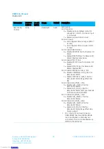
RSSI_Lag (EEPROM 0x67)
Controls a filter on the PWM output to smooth out the changes made to the PWM signal.
Setting the value to a very low number results in very quick changing output.
Setting the value to a higher number results in a slower varying PWM output.
Setting the value to 0x00 results in an instantaneous RSSI.
Because RSSI is measured per hop and the radio can hop over 43 or 79 hops, instantaneous RSSI may move
too quick to be of use as a signal strength indicator. The default value is 0x40 and should be sufficient for
most applications. It should be set to a value of less than 0x80.
RSSI_Lag affects the PWM Output according to the following equations:
Cumulative_Lag = Cumulati (RSSI_Current – Old_RSSI_Avg)
New_RSSI_Avg = Old_RS (Cumulative_Lag mod EE_Lag)
Cumulative_Lag is then stored in memory until the next time RSSI is calculated.
If (Cumulative_Lag mod EE_Lag) > 0, then Cumulative_Lag = remainder of (Cumulative_Lag mod EE_Lag)
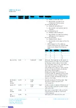
RSSI Output to PWM
A moving RSSI average can be written to the PWM Output as a signal strength indicator. The output pin to
use, the threshold range for the RSSI and the RSSI Type reported can all be configured through EEPROM
addresses.
The PWM output has a 39.3846 µS period. The duty cycle is set by the RSSI value recorded by the transceiver
and the RSSI Threshold High and RSSI Threshold Low values.
RSSI Threshold High (EEPROM 0x65)
The upper limit of the recorded RSSI reading. RSSI Values reported above this value (strong signals) report a
100% duty cycle on the PWM output.
To calculate the thresholds, use the following equation:
RSSI_Dec = (RS 82) * 2 +128
Then convert this from decimal to hexadecimal notation.
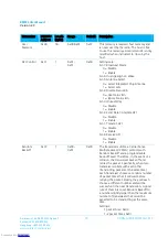
Sleep Indicator (EEPROM 0x45, bit 6)
When enabled, GIO_1 toggles low during sleep and high when the module is awake.
Sleep Timer High/Low (EEPROM 0xCD-0xCE)
Two bytes to indicate the length of time to sleep in seconds.
Downloaded from
Downloaded from
Downloaded from
Downloaded from
Downloaded from
Downloaded from
Downloaded from
Downloaded from
Downloaded from
Downloaded from
Downloaded from
Downloaded from
Downloaded from
Downloaded from
Downloaded from
Downloaded from
Downloaded from
Downloaded from
Downloaded from
Downloaded from
Downloaded from
Downloaded from
Downloaded from


