RM024 User Manual
Version 2.3
Americas: +1-800-492-2320 Option 2
Europe: +44-1628-858-940
Hong Kong: +852-2923-0610
www.lairdtech.com/wireless
8
CONN-GUIDE-RAMP24-0413
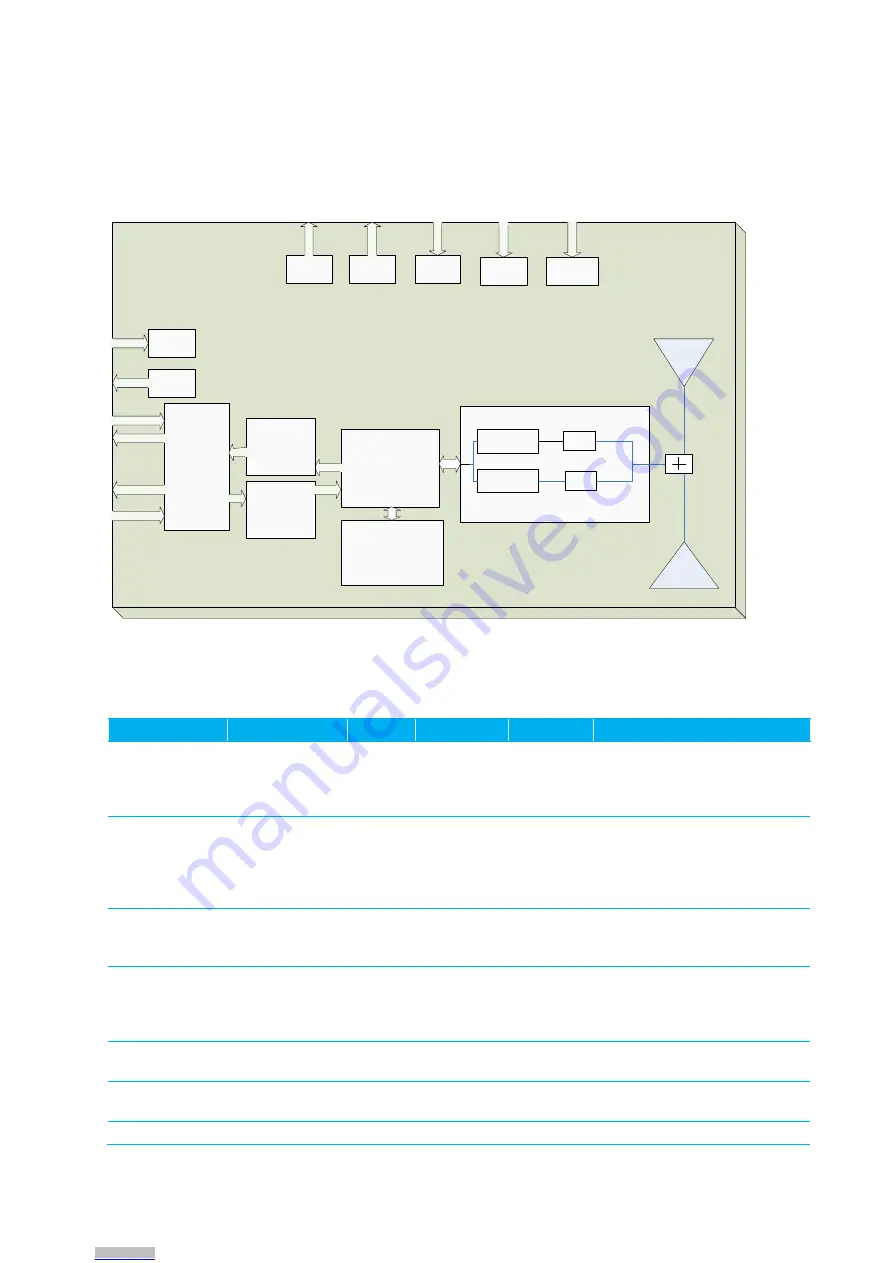
Block Diagram
Serial UART
EEPROM
Input Buffer
CPU
Transmitter
Receiver
U.FL
ADC
Force
9600
CMD/
Data
RXD
RTS
TXD
CTS
InRange
PWM
PA
uP_Reset
RM024
LNA
Output Buffer
DE/RE
Integrated
Antenna
RF Switch
Figure 1: Block Diagram of RM024
Timing Specifications
Table 5: Timing Specifications
Parameter
Server/Client
Min.
Typ.
Max.
Notes
Power on to
CTS Low
5 ms
10 ms
N/A
The first boot after a FW
upgrade will require more than
the typical amount of time for
CTS to toggle Low.
EEPROM Read
800 µs
1 ms
2 ms
Measured from last byte of
command to first byte of
response: 870 µs for 1 byte 1.1
ms for 80 bytes 1.4 ms for 256
bytes
EEPROM Write
20 ms
30 ms
40 ms
Measured. EEPROM writes will
cause the radio to
resynchronize
Power on to In
Range
Client only,
server will go in
range in fewer
than 13 ms
13 ms
600 ms
1700 ms
1
Maximum time assuming all
beacons are heard, RF
interference could extend the
maximum time indefinitely
Hope Period In
Range
13.19 ms
Hop Period Out
of Range
Client only
38.4 ms
Reset Pulse
250 ms
Downloaded from
Downloaded from
Downloaded from
Downloaded from
Downloaded from
Downloaded from
Downloaded from
Downloaded from

