Sentrius RG1xx
User Manual
Embedded Wireless Solutions Support Center:
http://ews-support.lairdtech.com
www.lairdtech.com/ramp
21
© Copyright 2017 Laird. All Rights Reserved
Americas: +1-800-492-2320
Europe: +44-1628-858-940
Hong Kong: +852 2923 0610
7.3
Radios
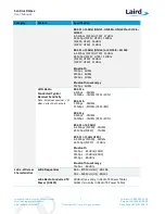
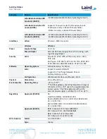
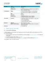
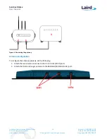
The radio page provides configuration of the radios and channels. The LoRa card has two radios (Radio 0 and
Radio 1). This interface allows advanced users to change radio and channel assignments within the allowed
range per the gateway region.
7.3.1
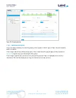
Channel Plan Graphic
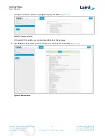
At the top of the Radios page is a graphic representation of the full bandwidth range, channels and radios. This
graphic is different for gateways operating in US mode and EU mode.
7.3.2
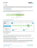
Radio Center Frequencies
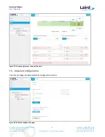
Each radio is assigned a center frequency. Channels are then assigned to each radio and given an offset from the
center (
Figure 23
).
Figure 23: Channel assignments
7.3.3
Channels
Channels are enabled and assigned to either radio. Each radio can have up to five channels assigned to it.
The channel’s frequency is an offset of its radio’s center frequency. For most channels with a 125 kHz
bandwidth, the offset can be -0.4 to +0.4 MHz.
Lora STD and FSK channels have configurable bandwidth. For these channels, when operating in 250 kHz or 500
kHz bandwidth, the offset can be -0.3 to +0.3 MHz.
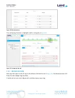
Each channel should be placed at least 200 kHz from any other channel, otherwise the channel’s bandwidth
overlaps. While this configuration still functions, there is wasted bandwidth. The interface displays a warning
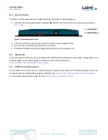
and marks each channel in red if they overlap. Channel configuration is shown in
Figure 24
.

