background image


32 

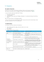
Re-packaging of the unit 


The unit has been emptied (see chapter 

11

). 

6) 

Lift the unit with a forklift or jack lift and place a transportable pallet under it. 

7) 

Enclose the unit including the transportable pallet with shrinking foil and shrink the foil tight. 


The unit is ready for transportation. 

Storing the Unit 

The storage area must be even and the unit should not stand on an edge or other obstructive object. 
The environmental conditions for storage of the unit or parts of it can be found in the specification 

paragraph on page 

16

. 

Disposal 

The unit was manufactured mainly from recyclable material. 


Make sure the components of the unit end up at a qualified company for disposal and recycling. 
Contact Laird Thermal Systems for take back of end-of-life units (see company contact on page 

7

 or 

ask a qualified company for disposal and recycling. 

Disposal of Operating Materials 

The operating materials of the unit can be hazardous to the environment and to health. 

  Make sure the operating materials are disposed of or recycled according to local regulations. 

  Also, the safety specifications of the coolant manufacturer must be obeyed. 

Return of the unit to Laird Thermal Systems 

NOTE 

Declaration of decontamination 

Before re-shipment of the unit a declaration of decontamination must be sent to Laird Thermal Systems. 


Summary of Contents for WL3004

Page 1: ...WL3004 Liquid to Air Cooling System Specification and User Manual Version 1 2 ...

Page 2: ... all liability for losses or damages resulting from use of or reliance on this information All Laird products are sold subject to the Laird Terms and Conditions of sale including Laird s limited warranty in effect from time to time a copy of which will be furnished upon request Copyright 2020 Laird Thermal Systems GmbH All Rights Reserved Laird Laird Technologies Laird Thermal Systems the Laird Lo...

Page 3: ... Guards 12 Caution Labels 12 In Case of Accidents 13 4 Product Description 14 Intended Use 14 Use not in Conformance with the Intended Use 14 Unit Components 15 Cooling Circuit 15 Specifications 16 Setting up Requirements 17 Infrastructure 17 5 Transport 18 Safety Indications for Transportation and Setting up 18 Transportation of the Unit 18 Unpacking 18 6 Initial Operation 19 Safety Indications R...

Page 4: ...r 27 Refilling of Coolant 27 Cleaning of Strainer 28 Cleaning of Unit Casing 29 10 Repair 30 11 Dismounting Disposal Storage 31 Temporary Placing out of Operation 31 Re packaging of the unit 32 Storing the Unit 32 Disposal 32 Disposal of Operating Materials 32 Return of the unit to Laird Thermal Systems 32 12 Wear Parts and Spare Parts 33 Addendum 35 Flow scheme 35 Wiring diagram 36 ...

Page 5: ...SCRIPTION NAME Page 1 2 04 22 20 Document template updated to LTS format spelling errors corrected Maria Mjalgard 1 1 03 22 19 Set point of temperature switch changed from 55 C to 45 C Jonathan Knutsson 16 1 0 07 31 19 Henrik Olsson ...

Page 6: ...installation putting into service operation repair or maintenance of the product by people that are not fully authorized Use of the product despite of defect wrongly implemented or non functional safety units or protective gear Unauthorized or forbidden modifications by the user concerning the electrical equipment of the unit Unauthorized or forbidden modifications by the user concerning the mecha...

Page 7: ...tact information given below Always communicate the following Your name and address Name of contact at your address Product data as on identification plate Type of unit serial number and year of manufacture Company contact Laird Thermal Systems Prumyslová 497 462 11 Liberec Czech Republic ...

Page 8: ...e number 387002779 3 Unit specifications Identification Plate The identification plate is attached to the front side of the unit see Fig 1 Fig 1 Position of identification plate 1 Identification plate Fig 2 Unit specific identification plate 1 Unit type 2 Article number 3 Serial number 4 Electrical specifications 5 Date of manufacture 1 5 2 3 4 1 ...

Page 9: ...in order to point out unpreventable residual risks when operating the unit These risks include danger for Human beings The unit and other equipment The environment The safety symbols used in this manual are indicated below The main reason for their use is to point the reader to the safety instruction given in the text field beside Symbol Meaning Warning with respect to general danger or damage to ...

Page 10: ...ll as any regional regulations Hints Regarding the Electrical Equipment When working on electrical installations the following principles should be observed Works on the electrical installations may only be accomplished by qualified electrical staff When connecting electrical equipment to mains regional regulations must be observed Be aware of the information in the wiring diagram The unit is powe...

Page 11: ...carried out only by trained experts All required information can be taken from the wiring diagram shown in the addendum Safety equipment must not be modified removed or taken out of operation All parts of the safety equipment must be accessible at all times Safety and Signaling Equipment included in the Unit The unit is equipped with safety equipment at critical spots see Fig 2 The water throughpu...

Page 12: ...he corresponding plate on the front side held by two screws For unscrewing screwing or opening closing of the fasteners a 7 0 x 1 0 mm slotted screwdriver is required Fig 4 Guards 1 Unit cover 2 Removable side panel 3 Access plate for electric terminal block Caution Labels Danger spots on the unit are indicated corresponding to German safety regulation BGV A8 Sicherheits und Gesundheitsschutzkennz...

Page 13: ...13 In Case of Accidents Should you or another person be injured when working with the unit Stay calm Render first aid Call the company first aider without exception ...

Page 14: ...cannot be granted When using the unit in a way not compliant with the intended use hazardous situations may occur Operation of the unit is not allowed under the following conditions The unit is used for a purpose other than the one it is intended for The unit or parts of it are damaged the electrical installation is not correct or the insulation is broken Protective or safety equipment is not func...

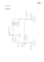
Page 15: ...coolant is driven by the pump to the device that is to be cooled and back via the return flow The heat is dissipated into the ambient air by an air cooled heat exchanger Exceedance of the maximum pump pressure is prevented by a by pass circuit The water temperature is controlled by an electric thermostat whereas water throughput is controlled by a flow control device Both indications are made pote...

Page 16: ...ity 3 0 kW Throughput 6 0 lpm at 6 0 bars Mains voltage 230 VAC 50 60 Hz Current draw 2 5 A 6 Performance data Environmental conditions Operating temperature 5 C 40 C Storage temperature 25 C 70 C empty Relative humidity 20 80 7 Environmental conditions Settings Flow control device 4 0 0 1 lpm opening threshold Thermal switch 45 C 5 C tolerance 15 C hysteresis Maximum pressure 8 0 0 5 bars 8 Setti...

Page 17: ... through unsuitable environmental conditions Damage to property and corrosion damage may result and are not covered by manufacturer s liability The unit is only authorized for use in indoor environments The unit must not be stored or operated in aggressive humid environments The unit must not be stored or operated outdoor Pay attention to the environmental conditions as given in the specifications...

Page 18: ...e pallet Leave the unit on the pallet until bringing it into service Use a forklift or jack lift for transportation to the installation location Unpacking Remove the foil before setting up the unit Inspect the unit regarding Damage caused by transportation Completeness of delivery Lift the unit with a forklift or jack lift off the transportable pallet Dispose of the packaging material in accordanc...

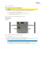
Page 19: ... page 9 Setting to Work Placement Fig 7 Minimum clearance for air entrance and air exit 1 Ventilation grid 1 Move the unit to its installation location as mentioned in chapter 5 2 Place the unit in a way that air entrance and air exit are not obstructed Wall clearance must not be less than 0 5 m otherwise cooling capacity may be restricted NOTE In case of storage of the unit at temperatures lower ...

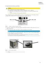
Page 20: ...nlet are indicated with respective symbols Fig 8 Labeling of water inlet and water outlet 1 Connect a suitable hose to the hose nipples for water inlet and water outlet and secure it with a clamp respectively 2 Connect the hoses to the corresponding nipples of the device to be cooled NOTE When connecting the cooling hoses pay attention to flow direction Follow the documentation released by the man...

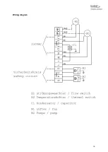
Page 21: ... or short circuiting CAUTION Risk of damage through improper connections Improper integration of the unit into the safety circuit of the device to be cooled will lead to the inoperativeness of the safety equipment listed in chapter 3 on page 11 All connections required must be incorporated according to the wiring diagram shown in the addendum Ensure yourself that all connected safety equipment is ...

Page 22: ...e the cap on the coolant container 2 Switch on the unit and let it run for about 10 minutes in order to fill and vent the cooling circuit Continuously check the filling level during this procedure 3 If required refill coolant 4 Check the compliance with the operational parameters as specified on page 16 5 Remount cap on coolant container 6 Switch off the unit The unit is ready for operation Daily ...

Page 23: ...rior to operation of the device to be cooled using the appropriate control of that device 2 Check the compliance with the operational data according to the specifications listed on page 16 The unit is running Switching off the Unit Cooling operation has come to an end 1 Switch off the unit using the control of the device to be cooled 2 Close all valves that may exist in the extension of the hoses ...

Page 24: ...trol device contains a closing contact whose OFF threshold is pre set to a throughput of 4 0 liters per minute For setting the switching point the switch head must be adjusted For that purpose the screw retained by red locking varnish must be released and the switching head must be moved while the throughput change is monitored by means of the equipment implemented for that purpose After setting t...

Page 25: ... The thermal switch can be adapted to meet changing needs Increase the temperature setpoint 2 Turn the knob clockwise The switch off temperature is set to a higher value Decrease the temperature setpoint 3 Turn the knob counter clockwise The switch off temperature is set to a lower value ...

Page 26: ...ouble shooting table given below Problem Possible reason Countermeasure The unit does not start Electrical connection not correct or no mains connection Check connection insert mains plug check main power switch The unit is running but cooling capacity is not available or too low External hoses sharply bent Pay attention to smooth bends when hoses are connected Unit properly located Clearance to w...

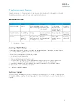
Page 27: ...sonnel 11 Maintenance schedule Cleaning of Heat Exchanger Cooling capacity is heavily reduced if the heat exchanger is polluted The heat exchanger must be checked for pollution regularly and be cleaned if required For cleaning the heat exchanger follow these steps 4 Disconnect the unit from mains 6 Remove the side panel and the unit cover 7 Clean the heat exchanger using compressed air opposite to...

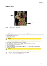
Page 28: ... and screw on the cover 7 Re open the ball valve 8 Should any coolant leak from the strainer the cover must be screwed on using a little more force 9 Remount the side panel 10 Start up the unit for venting the cooling circuit see page 22 11 Check the coolant level and refill if required CAUTION A small amount of coolant will leak from the pump Use a cloth or an appropriate vessel for absorption CA...

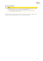
Page 29: ... all the plates at the unit are always clean and legible CAUTION Risk of damage through use of improper cleansing material When using aggressive or abrasive cleaning agents corrosion may occur as result of a damaged paint film For cleaning the unit casing only use mild cleaning agents e g dish washing detergents Use clean and lintless cloth for cleaning ...

Page 30: ...ranty has expired no restrictions from the side of Laird Thermal Systems exist with respect to repair work carried out by the customer as long as guarantee and warranty conditions remain untouched In any case only expert staff is authorized for doing repair work NOTE When doing repair work on the unit always be aware of the safety regulations as defined on page 9 ...

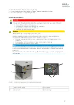
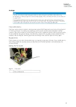
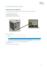
Page 31: ...ing operation is finished 1 Disconnect the unit from mains 2 Remove all cabling from the unit 3 Remove all hoses to and from the unit Fig 13 Drain with cap 1 Cap NOTE The coolant must be collected and disposed of according to valid regulations 4 Let the coolant container run empty into an appropriate vessel 5 Clean the unit The unit is placed out of operation 1 ...

Page 32: ... manufactured mainly from recyclable material Make sure the components of the unit end up at a qualified company for disposal and recycling Contact Laird Thermal Systems for take back of end of life units see company contact on page 7 or ask a qualified company for disposal and recycling Disposal of Operating Materials The operating materials of the unit can be hazardous to the environment and to ...

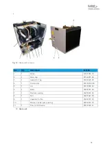
Page 33: ...e parts made by manufacturers other than Laird Thermal Systems NOTE Identification data concerning the unit and spare parts The type of unit and the article number can be found on the identification plate of the unit The corresponding numbers in Fig 12 as well as the part descriptions are listed in the spare part list Please direct your inquiries and orders to Laird Thermal Systems contact see pag...

Page 34: ...91729015 00 3 1 Gasket for cap 93300405 00 4 1 Thermostat 387002780 00 5 1 Lid 95179904 00 6 1 Motor 95205201 00 7 1 Flexible coupling 95205203 00 8 1 Fan 95251621 00 9 1 Capacitor for fan 95290701 00 10 Strainer inside pump casing 96299012 00 11 1 Flow control device 95140538 01 12 Spare parts ...

Page 35: ...35 Addendum Flow scheme ...

Page 36: ...36 Wiring diagram ...

Page 37: ...37 ...

Reviews: