FENCE
The fence (A) Fig. 10, can be moved in or out by loosening lever (B), sliding fence to the desired position
and tightening lever (B).
NOTE:
Lever (B) is spring-loaded and can be repositioned by pulling out on the lever and
repositioning it on the serrated nut located underneath the lever.
DEPTH STOP
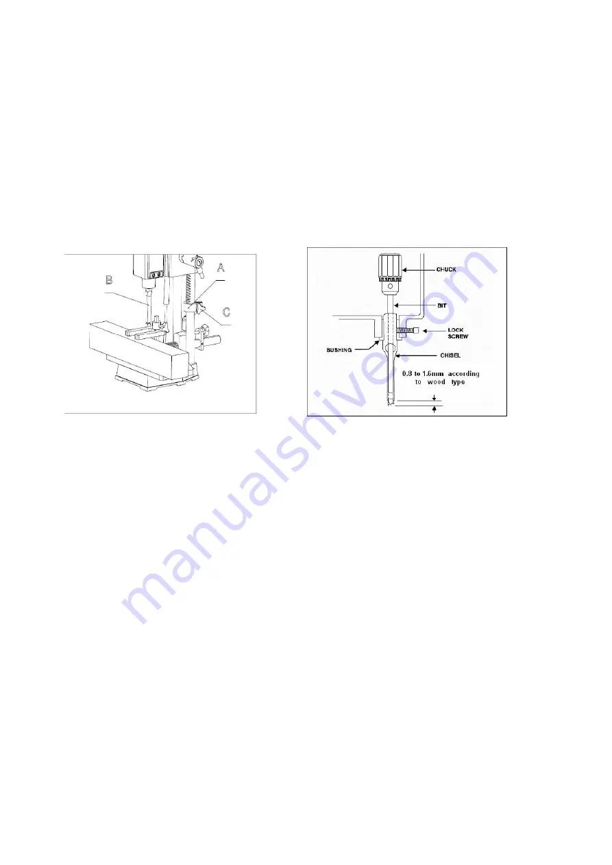
A depth stop guide (A) Fig. 11, is provided to limit the depth of the chisel (B). To adjust the depth stop guide (A), loosen
screw (C) and lower head until the chisel (B) is at the desired depth. Lower depth stop guide (A) until it is at the desired
depth , tighten screw (C).
Fig 11
Fig 12
INSTALLING CHISEL & BIT
1.
Loosen lock screw, shown in Figure 12.
2. Insert chisel bushing (with the hole facing forward) into the head. Tighten the screw just
enough to hold the chisel in place.
!
NOTE: Set the slot in the side of the chisel
to the left or right,
NOT to the front or back. This will allow chips to escape
when cutting mortises.
3. Push the chisel up as far as possible into the head. Then lower the chisel approximately 0.8mm to 1.6mm, depending
on the type of wood being worked. Tighten the screw to hold chisel in place.
4. Push bit up through the chisel opening as far as it will go. Lock the drill bit in place with the chuck key.
5. Loosen screw and push chisel up against the bushing, then tighten screw. This should provide
the proper distance between the points of the chisel and the bit.
MAINTENANCE
The Mortiser requires only minor maintenance, such as cleaning and lubrication and routine adjustment and sharpening
of the chisel and bit.
Summary of Contents for MS36127A3
Page 12: ...Parts Diagram ...
Page 13: ...Parts List ...


