background image

Lake Shore Model 1015 User’s Manual

2-4

Installation

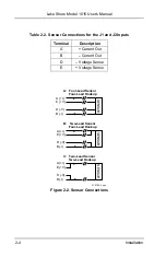
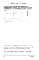
Table 2-2. Sensor Connections for the J1 and J2 Inputs

Terminal

Description

A

+ Current Out

B

– Current Out

D

– Voltage Sense

E

+ Voltage Sense

SENSOR

A (+I)
E (+V)

D (-V)
B (-I)

C: Two-Lead Sensor

Two-Lead Hookup

SENSOR

A (+I)
E (+V)

D (-V)
B (-I)

B: Two-Lead Sensor

Four-Lead Hookup

SENSOR

A (+I)
E (+V)

D (-V)
B (-I)

A: Four-Lead Sensor

Four-Lead Hookup

F-1015-2-2.eps

Figure 2-2. Sensor Connections

Summary of Contents for 1015

Page 1: ...Cryotronics Inc No government or other contractual support or relationship whatsoever has existed which in any way affects or mitigates proprietary rights of Lake Shore Cryotronics Inc in these developments Methods and apparatus disclosed herein may be subject to U S Patents existing or applied for Lake Shore Cryotronics Inc reserves the right to add improve modify or withdraw functions design mod...

Page 2: ...ons for any product or part or buyer supplied software interfacing THIS WARRANTY IS IN LIEU OF ANY OTHER WARRANTIES EXPRESSED OR IMPLIED INCLUDING MERCHANTABILITY OR FITNESS FOR A PARTICULAR PURPOSE WHICH ARE EXPRESSLY EXCLUDED THE OWNER AGREES THAT LAKE SHORE S LIABILITY WITH RESPECT TO THIS PRODUCT SHALL BE SET FORTH IN THIS WARRANTY AND INCIDENTAL OR CONSEQUENTIAL DAMAGES ARE EXPRESSLY EXCLUDED...

Page 3: ...nd Unpacking 2 1 2 2 Repackaging For Shipment 2 1 2 3 Power and Ground Requirements 2 2 2 4 Bench Use 2 2 2 5 Rack Mounting 2 3 2 6 Sensor Input Connections 2 3 2 7 Environmental Requirements 2 3 3 OPERATION 3 1 3 1 Controls and Indicators 3 1 3 2 Operation 3 3 3 2 1 HI LO Power Selection 3 3 3 2 2 Power ON OFF 3 3 3 2 3 SINGLE Cycle Operation 3 3 3 2 4 CONTINUOUS Cycle Operation 3 4 4 MAINTENANCE...

Page 4: ...ck Configuration 2 3 2 2 Sensor Connections 2 4 3 1 Model 1015 Front Panel 3 1 3 2 Model 1015 Rear Panel 3 2 LIST OF TABLES Table No Title Page 1 1 Model 1015 Specifications 1 2 2 1 Line Voltage Selection 2 2 2 1 Sensor Connections for the J1 and J2 Inputs 2 3 B 1 Comparison of Liquid Helium to Liquid Nitrogen B 1 ...

Page 5: ...odel 1015 contains two temperature monitoring circuits to control each heater channel The Model 1015 monitors the temperature of each stage via the diode temperature sensors mounted on each and automatically shuts down when each of the stages reaches room temperature There are two different power levels available for each channel to accommodate different test set ups or heating requirements a low ...

Page 6: ...s subject to change without notice 1 2 ELECTROSTATIC DISCHARGE Electrostatic Discharge ESD is a transfer of electrostatic charge between bodies at different electrostatic potentials caused by direct contact or induced by an electrostatic field It may damage electronic parts assemblies and equipment The low energy source that most commonly destroys Electrostatic Discharge Sensitive ESDS devices is ...

Page 7: ... inserting or removing a device or assembly from a container must maintain contact with a conductive portion of the container Use only plastic bags approved for storage of ESD material 6 Do not handle ESDS devices unnecessarily or remove from the packages until actually used or tested 1 3 SAFETY SUMMARY Observe these general safety precautions during all phases of instrument operation service and ...

Page 8: ...nstrument Do not install substitute parts or perform any unauthorized modification to the instrument Return the instrument to an authorized Lake Shore Cryotronics Inc representative for service and repair to ensure that safety features are maintained 1 4 SAFETY SYMBOLS Direct current power line Alternating current power line Alternating or direct current power line Three phase alternating current ...

Page 9: ...s freight damage to the instrument file proper claims promptly with the carrier and insurance company and notify Lake Shore Notify Lake Shore immediately of any missing parts Lake Shore cannot be responsible for any missing parts unless notified within 60 days of shipment 2 2 REPACKAGING FOR SHIPMENT To return the Model 1015 or accessories for repair or replacement obtain a Return Goods Authorizat...

Page 10: ... personnel the National Electrical Manufacturer s Association NEMA recommends and some local codes require instrument panels and cabinets be gounded This instrument is equipped with a three conductor power cable which when plugged into an appropriate receptacle grounds the instrument Table 2 1 Line Voltage Selection Line Voltage Volts Operating Range Volts Slow Blow Fuse Amps 100 90 105 5 0 120 10...

Page 11: ...the alternate two wire connection Figure 2 1B in less critical applications where lead resistance is small and small readout errors can be tolerated Lake Shore 36 Gauge Cryogenic wire is ideal for sensor connections The four Phosphor Bronze leads with Formvar insulation are bonded together and color coded red green clear and blue for easy wire identification 2 7 ENVIRONMENTAL REQUIREMENTS WARNING ...

Page 12: ...puts Terminal Description A Current Out B Current Out D Voltage Sense E Voltage Sense SENSOR A I E V D V B I C Two Lead Sensor Two Lead Hookup SENSOR A I E V D V B I B Two Lead Sensor Four Lead Hookup SENSOR A I E V D V B I A Four Lead Sensor Four Lead Hookup F 1015 2 2 eps Figure 2 2 Sensor Connections ...

Page 13: ...N HI ON LO FIRST STAGE READY WAIT POWER ON HI ON LO SECOND STAGE STOP 2 1015 WARM UP POWER SUPPLY F 1015 3 1 eps First Stage Block Annunciated POWER READY and WAIT indicators and power setting selection for the First Stage Second Stage Block Annunciated POWER READY and WAIT indicators and power setting selection for the Second Stage START STOP Annunciated START STOP warm up cycle operation Power O...

Page 14: ...r input line voltage selection and fuse J1 Input connector for the First Stage sensor J2 Input connector for the Second Stage sensor J3 and J4 Heater Output for the First Stage J5 and J6 Heater Output for the Second Stage Configuration Switch DIP switch selection of SINGLE or CONTINUOUS cycle operation 10 5 and 1 minute cycle delay times timeouts Figure 3 2 Model 1015 Rear Panel ...

Page 15: ...ing room temperature the Model 1015 shuts off heater output to that stage and does not allow it to go back on To select the SINGLE cycle operation switch the rear panel CONT switch to the down position To initiate the warm up cycle press the front panel START button The START LED lights and the unit monitors the First and Second stage sensor inputs to determine if they are already at room temperat...

Page 16: ...hes in the up position selects a 10 minute timeout To initiate the warm up cycle press the front panel START button The START LED lights and the unit monitors the First and Second stage temperatures to determine if they are at room temperature If they are the yellow WAIT LED lights and the unit monitors the stage temperature for the timeout period If the stage is still at room temperature after th...

Page 17: ...C operation Use slow blow fuses 5 Replace fuse holder and compartment cover and connect the power cord 4 2 Line Voltage Configuration The rear panel 3 pronged line power connector permits Model 1015 operation at either 115 or 230 VAC The configuration is indicated on rear panel in the Line Voltage Selection Block Use the procedure below to change line voltage WARNING To prevent shock hazard turn o...

Page 18: ...Lake Shore Model 1015 User s Manual 4 2 Maintenance This Page Intentionally Left Blank ...

Page 19: ...American Standard Code for Information Exchange ACSII A standard code used in data transmission in which 128 numerals letters symbols and special control codes are represented by a 7 bit binary number as follows asphyxiant gas A gas which has little or no positive toxic effect but which can bring about unconsciousness and death by displacing air and thus depriving an organism of oxygen baud A unit...

Page 20: ...ystem of units SI A universal coherent system of units in which the following seven units are considered basic meter kilogram second ampere kelvin mole and candela The International System of Units or Système International d Unités SI was promulgated in 1960 by the Eleventh General Conference on Weights and Measures For definition spelling and protocols see Reference 3 for a short convenient guide...

Page 21: ...uctive alloy with a transition temperature typically near 9 K in zero magnetic field National Institute of Standards and Technology NIST Government agency located in Gaithersburg Maryland and Boulder Colorado that defines measurement standards in the United States parts per million ppm 4 x 10 6 is four parts per million pounds per square inch psi A unit of pressure 1 psi 6 89473 kPa Variations inc...

Page 22: ...rt kelvin to Celsius subtract 273 15 To convert Celsius to Fahrenheit multiply C by 1 8 then add 32 or F 1 8 x C 32 To convert Fahrenheit to Celsius subtract 32 from F then divide by 1 8 or C F 32 1 8 References 1 Sybil P Parker Editor Dictionary of Scientific and Technical Terms Third Edition New York McGraw Hill 1969 IBSN 0 395 20360 0 2 Christopher J Booth Editor The New IEEE Standard Dictionar...

Page 23: ...5 77 0 013 152 0 78 B3 0 HANDLING CRYOGENIC STORAGE DEWARS All cryogenic containers dewars must be operated in accordance with the manufacturer s instructions Safety instructions will also be posted on the side of each dewar Cryogenic dewars must be kept in a well ventilated place where they are protected from the weather and away from any sources of heat B4 0 LIQUID HELIUM AND NITROGEN SAFETY PRE...

Page 24: ...ipes or equipment Long sleeve shirts and cuffless trousers that are of sufficient length to prevent liquid from entering the shoes are recommended B5 0 RECOMMENDED FIRST AID Every site that stores and uses LHe and LN2 should have an appropriate Material Safety Data Sheet MSDS present The MSDS may be obtained from the manufacturer distributor The MSDS will specify the symptoms of overexposure and t...

Page 25: ... NOTES ...

Page 26: ...netic measurement and test systems Since 1968 Lake Shore physicists material scientists and engineers have dedicated themselves to the development of tomorrow s technology today Lake Shore serves a worldwide network of Customers including university and national laboratories aerospace and other industries as well as many of the premier companies in the world ...

Reviews: