Lake Shore Model 321 Autotuning Temperature Controller User’s Manual
Installation
2-3
2.4 ENVIRONMENTAL
REQUIREMENTS
The Model 321 is intended for laboratory use. In order to meet and maintain specifications, the
Model 321 should be operated at an ambient temperature range of 20 to 30 °C (68 to 86 °F). The
unit may be operated within the range of 15 to 35 °C (59 to 95 °F) with reduced accuracy.
WARNING:
To prevent electrical fire or shock hazards, do not expose this instrument to rain or excess
moisture.
2.5 GROUNDING AND SHIELDING
To protect operating personnel, the National Electrical Manufacturer’s Association (NEMA)
recommends, and some local codes require, instrument panels and cabinets be grounded. This
instrument is equipped with a three-conductor power cable which, when plugged into an appropriate
receptacle, grounds the instrument.
Grounding and shielding of signal lines are major concerns when setting up any precision instrument or
system. The Model 321 allows 4-wire measurement of diode voltage and resistance. To prevent
inaccurate measurements, diode and resistive sensor leads must be isolated from earth ground.
Thermocouple sensors, however, may be grounded. Shield sensor cables whenever possible. Attach
the shields to the shield pin provided in the connector. Do not attach the shield at the sensor end.
The heater output is isolated from earth ground. To prevent heater noise coupling into the
measurement, do not allow the heater output to contact earth ground. Earth ground (GND) is provided
on the rear panel for shielding purposes only.
Digital logic in the Model 321 is tied directly to earth ground for interface communications. The sensor
lines and digital communication lines should be separated whenever possible to prevent excess noise
in the measurement.
2.6 SENSOR INPUT SETTINGS
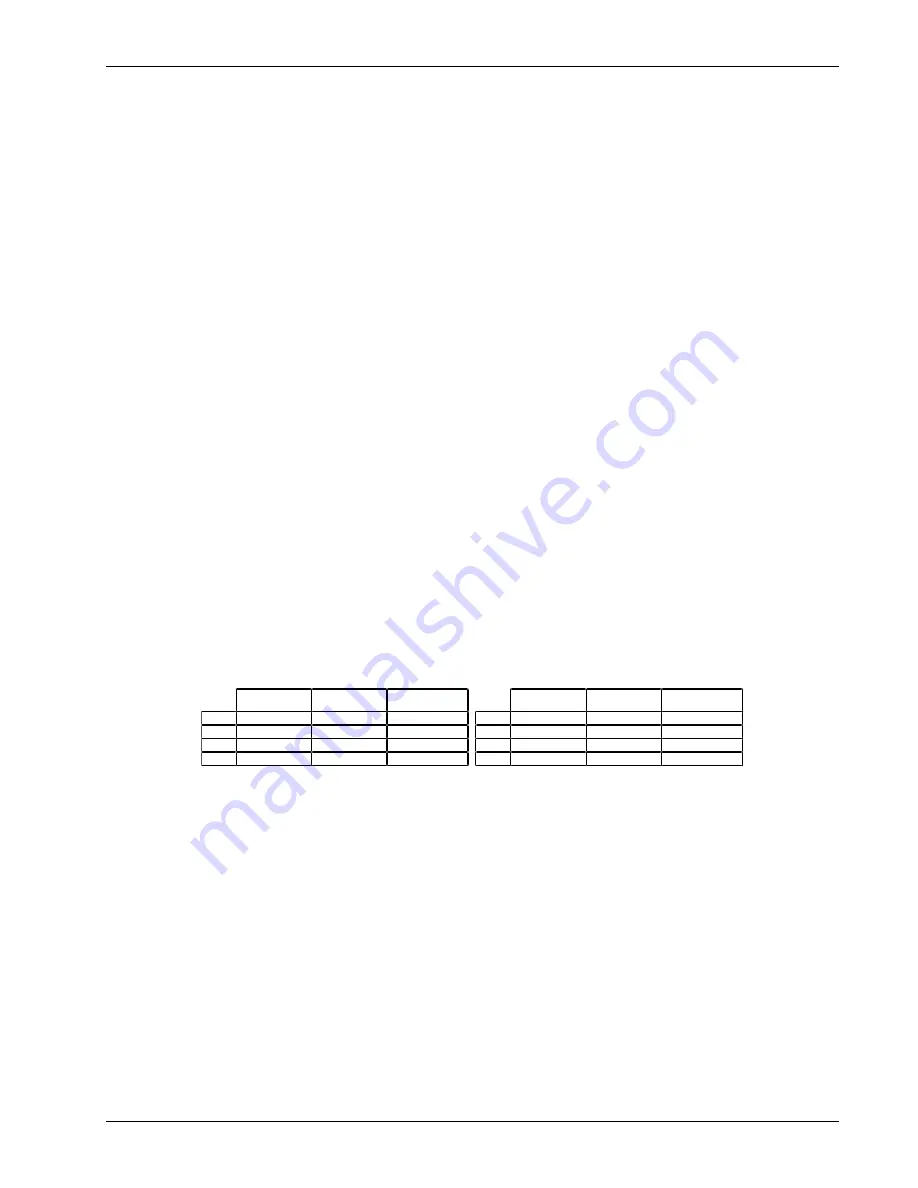
The sensor input type is established at the factory before shipping. Sensor input type is configured by
setting DIP switches S1 and S2 on the main PCB inside the unit. If you wish to check the DIP switch
settings, the configurations are as follows.
DIP Switch S1
*
DIP Switch S2
*
*
To change sensor input type, DIP switches on S1 and S2 must be switched identically.
Silicon Diode
(Model 321-01)
Platinum
(Model 321-02)
Thermocouple
(Model 321-04)
S1-1
Closed
Open
Open
S1-2
Open
Closed
Open
S1-3
Open
Open
Closed
S1-4
Open
Open
Closed
Silicon Diode
(Model 321-01)
Platinum
(Model 321-02)
Thermocouple
(Model 321-04)
S2-1
Closed
Open
Open
S2-2
Open
Closed
Open
S2-3
Open
Open
Closed
S2-4
Open
Open
Closed
To change the DIP Switch settings, refer to Paragraph 6.7. The Model 321 must be recalibrated when
switched between sensor input types.
Diode and Platinum connections are defined in Paragraph 2.7.1. Thermocouple connections are
described in Paragraph 2.7.2. Finally, thermocouple compensation is discussed in Paragraph 2.7.2.1.

