Lake Shore Model 321 Autotuning Temperature Controller User’s Manual
3-2
Operation
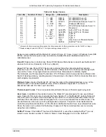
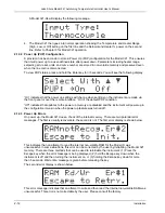
Ramp Rate
Allows the user to set the rate at which the temperature setpoint increases or
decreases when the user changes the setpoint value. Refer to Paragraph 3.3.3.
Curve
Used to select the sensor response curve. Refer to Paragraph 3.2.5.
SoftCal™
Permits the user to improve the accuracy of the silicon diode sensor by setting up a
special modification to the Standard Curve 10. Refer to Paragraph 3.2.6.
Zone Setting
The user is able to enter up to 10 temperature zones where the controller will
automatically use preprogrammed PID settings and Heater Ranges. Refer to
Paragraph 3.3.6.
Baud
If the Serial Interface is being used, the Baud Rate of the Model 321 may be
selected from 300 or 1200 by pressing this button. Refer to Paragraph 3.4.1.
Analog Out
Use this button to set the scaling of the analog output. The default is 0 to 10 volts
corresponding to 0 to 1000 K. A user defined output scaling can also be specified.
Refer to Paragraph 3.4.2.
AutoTune
The controller has the capability of automatically setting P, PI, or PID values. Refer
to Paragraph 3.3.4.
P
For manual adjustment of controller gain (
P
roportional). Refer to Paragraph
3.3.5.1.
I
For manual adjustment of reset (
I
ntegral). Refer to Paragraph 3.3.5.2.
D
For manual adjustment of rate (
D
erivative). Refer to Paragraph 3.3.5.3.
Escape
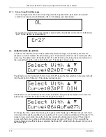
The
Escape
button is used to terminate a function without making changes to the
existing settings. Pressing and holding the
Escape
button for
≈
5 seconds resets
the controller, returning most parameters to factory default values. Refer to
Paragraph 3.4.3.
s
The up triangle (
s
) serves two functions. The first is to toggle between various
settings shown in the display. The second is to increment a numerical display.
s
The down triangle (
t
) serves two functions. The first is to toggle between various
settings shown in the display. The second is to decrement a numerical display.
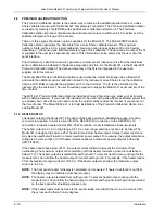
Enter
The
Enter
button is used to accept changes made in the field display. Press and
hold the
Enter
button to gain access to the Power Up (PUP) configuration setup
display. Refer to Paragraph 3.4.4.
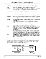
3.1.2 Two Row by Sixteen Character Liquid Crystal Display (LCD)
In normal operation, the two row by sixteen character display provides a temperature reading and
heater status on the top row and the current temperature setpoint and heater output status on the
bottom row. Other information is displayed when using the various functions on the keypad. Each
character is comprised of a 5 by 7 dot matrix. See Figure 3-2.
Temperature Reading
Units:
K, C, V, mV,
9
9
Heater Range
Temperature Setpoint
Heater %
C-321-3-2.eps
Figure 3-2. Definition of 2 by 16 Display

