Lake Shore Model 331 Temperature Controller User’s Manual
8.9 CALIBRATION
PROCEDURE
The Model 331 requires calibration of both of the sensor inputs and analog output to operate within
specification. None of the other circuits require calibration. The sensor inputs may be configured as
diode/resistor or thermocouple and the calibration process differs for each. This procedure contains
instructions for both input types. The analog output calibration is necessary for the Model 331S only
and may be ignored for the Model 331E. Refer to Paragraph 8.9.5 for details on calibration specific
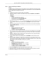
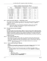
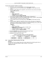
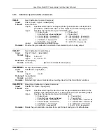
interface commands.
8.9.1
Equipment Required for Calibration
PC and Interface
• PC with software loaded which provides serial command line communication.
(Example program in Paragraph 6.2.7 is ideal for this purpose.)
• DE-9 to DE-9 cable. Pin to pin connections on all 9 pins. Female connectors on both ends.
• DE-9 null modem adapter.
Test and Measurement Equipment
• Digital Multimeter (DMM) with minimum of 6-digits resolution. DMM DC voltage and 4-lead
resistance specifications to be equivalent to or better than HP 3458A specifications.
• Precision reference providing up to ±7.5 V with 1 mV resolution for Diode/Resistor input
calibration.
• Precision reference providing up to ±50 mV with 1 µV resolution for Thermocouple input
calibration.
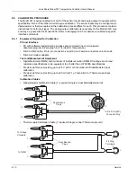
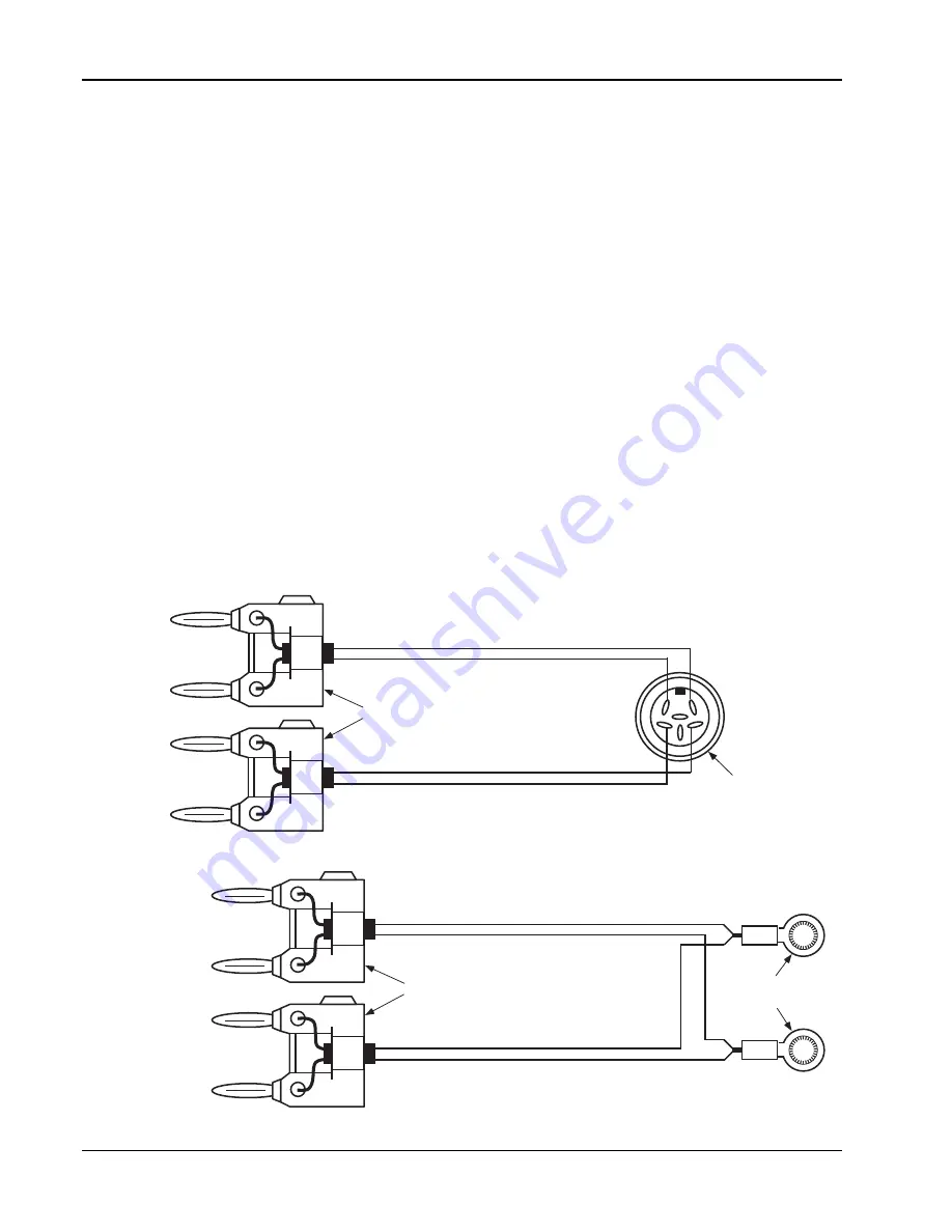
Calibration Cables
• Diode/Resistor Calibration Cable (1 required if single or dual Diode/Resistor unit)
2
3
5
1
4
6
I+
I
V
V+
I+
I
V
V+
6-Pin DIN (240°)
Connector Plug
Dual Banana
Plugs
• Thermocouple Calibration Cable (1 required if single or dual Thermocouple unit)
+
+
Dual Banana
Plugs
To Voltage
Standard
To DMM
#4 Ring
Terminals
+
8-10
Service

