Lake Shore Model 331 Temperature Controller User’s Manual
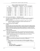
Equipment Required for Calibration (Continued)
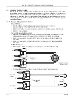
Resistor Standards
• Resistor standards with the following nominal values. If standards are not available, ¼ W
25ppm/
o
C metal film resistors can be used. They should have connectors attached to mate with
two dual banana plugs for 4-lead measurement.
• 0
Ω
(short), 10
Ω
, 100
Ω
, 500
Ω,
1 k
Ω,
5 k
Ω,
100 k
Ω.
Miscellaneous
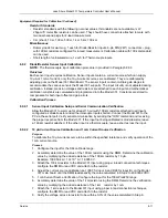
• Dummy loads for warm up, 1 each for Diode/Resistor inputs: 6-pin DIN (240°) connectors – plug,
with 100 k
Ω
resistors configured for 4-lead measurement. Calibration cable with 100 k
Ω
standard
can be used.
• Short length of uninsulated wire, 1 each for Thermocouple inputs.
8.9.2
Diode/Resistor Sensor Input Calibration
NOTE:
The thermocouple input calibration procedure in provided in Paragraph 8.9.3.
Overview
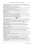
Each sensor input requires calibration. Sensor Inputs contain a current source which can supply
10 µA or 1 mA of current, only the 10 µA current sources are calibrated. They are calibrated by
adjusting pots on the Model 331 Main Board. The sensor inputs contain multiple gain stages to
accommodate the various sensors the Model 331 supports. The input circuitry is not adjusted during
calibration. Instead, precision voltages and resistors are attached to each input and mathematical
calibration constants are calculated and programmed into the Model 331. Constants are stored to
compensate for both input offset and gain errors.
Calibration Process
8.9.2.1
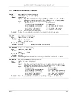
Sensor Input Calibration Setup and Serial Communication Verification
Allow the Model 331 to warm up for at least 1 hour with 100 k
Ω
resistors attached to all inputs
configured as diode/resistor and all thermocouple inputs shorted. Connect the Model 331 to the
PC via the serial port. Verify serial communication by sending the *IDN? command and receiving
the proper response from the Model 331. If the input not being calibrated is diode/resistor, leave
a 100 k
Ω
resistor attached. If the other input is a thermocouple, leave a short across the input.
8.9.2.2
10 µA Current Source Calibration and 1 mA Current Source Verification
Purpose
To calibrate the 10 µA current source to be within the specified tolerance and verify operation of the
1 mA current source.
Process
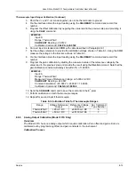
1. Configure the input for the Silicon Diode range.
2. Accurately determine the value of the 100 k
Ω
resistor using the DMM. Determine the calibration
value by multiplying the actual resistance of the 100 k
Ω
resistor by 10 µA.
Example: 100.050 k
Ω
× 10×10
–6
A = 1.00050 V.
3. Attach the 100 k
Ω
resistor to the Model 331 input using proper 4-lead connection techniques,
configure the DMM to read VDC and attach to the resistor.
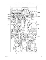
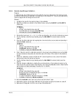
4. Adjust the current source calibration pot, (R97 for Input A and R98 for Input B), on the Model
331 main board until the DMM reads exactly the value calculated in Step 2 to ±0.00002 VDC.
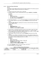
5. 1 mA Current Source Verification. Configure the input for the 100
Ω
Plat/250 range.
6. Accurately determine the value of the 1 k
Ω
resistor using the DMM. Determine the verification
value by multiplying the actual resistance of the
1
k
Ω
resistor by 1 mA.
7. Attach the 1 k
Ω
resistor to the Model 331 input using proper 4-lead connection techniques,
configure the DMM to read VDC and attach to the resistor.
8. Verify the voltage across to resistor to be within ±0.3% of the value calculated in Step 6.
Service
8-11


