Lake Shore Model 331 Temperature Controller User’s Manual
Thermocouple Input Ranges Calibration (Continued)
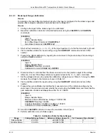
3. Short the V+ and V– terminals together, do not tie the terminals to ground.
4. Via the interface obtain the input reading using the
CALREAD?
command and record this
number.
5. Program the offset calibration by negating the value read in the previous step and providing it
using the
CALZ
command.
EXAMPLE:
Input: A
Range: Thermo/25mV
CALREAD?
Reading: -00.0122
Calibration Command:
CALZ A,6,+0.0122
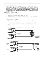
6. Connect input to standard and DMM with cable described in Paragraph 8.9.1.
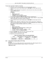
7. Set the voltage reference to provide the calibration voltage shown in Table 8-3. Using the DMM
measure the voltage to the tolerance shown in Table 8-3.
8. Via the interface obtain the input reading using the
CALREAD?
command and record this
number.
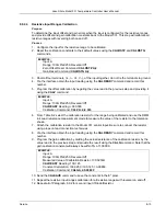
9. Program the gain calibration by dividing the measured value of the reference voltage by the
value read in the previous step and provide the result using the
CALG
command. Note that the
gain calibration constant will always be within 5% of 1.00000.
EXAMPLE:
Input: A
Range: Thermo/25mV
Measured Value of Reference Voltage: +25.0032 mV DC
CALREAD?
Reading: +24.9867
Constant Calculation: +25.0032 / +24.9867 = 1.00066
Calibration Command:
CALG A,6,1.00066
10. Send the
CALSAVE
command to save the constants in the E
2
prom.
11. Perform calibration on both thermocouple ranges.
12. Repeat for second input if thermocouple.
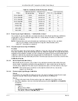
Table 8-3. Calibration Table for Thermocouple Ranges
Range Voltage
Reference
Output
Reference Voltage
Known to
Cal. Command
Type Number
Thermo/25mV
+25 mV DC
±0.0070 mV DC
6
Thermo/50mV
+50 mV DC
±0.0130 mV DC
7
8.9.5
Analog Output Calibration (Model 331S Only)
Overview
The Model 331S has one analog output which requires calibration. Zero offset and gain errors are
calibrated out by programming offset and gain constants to the instrument.
Calibration Process
Service
8-15

