Lake Shore Model 331 Temperature Controller User’s Manual
4.6 TEMPERATURE
CONTROL
There are many steps involved in setting up a temperature control loop. Chapter 2 of this manual
describes the principals of closed loop (feedback) control. Chapter 3 describes necessary hardware
installation. The following sections of this chapter describe how to operate the control features and set
control parameters. Each control parameter should be considered before enabling a control loop or the
instrument may not be able to perform the most simple control functions. A good starting point is
deciding which control loop to use, whether to operate in open or closed control mode and which tuning
mode is best for the application. Other parameters fall into place once these have been chosen.
4.6.1 Control
Loops
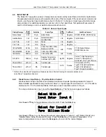
The Model 331 is capable of running either one (331E) or two simultaneous (331S) control loops.
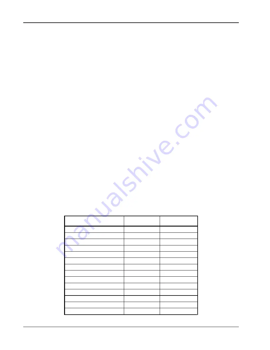
Their capabilities are compared in Table 4-3. As shown there the primary difference between the two
loops is their control output.
Loop 1:
Loop 1, the primary control loop, is the traditional control loop for a cryogenic temperature
controller. It includes the largest set of hardware and software features making it very flexible and
easy to use. Loop 1 uses the heater output as its control output giving it several advantages. The
heater output is a well regulated 50 W DC output with three power ranges. This provides quiet, stable
control for a broad range of temperature control systems in a fully integrated package.
Loop 2:
Loop 2, the auxiliary control loop (331S only), shares most of the operational features of loop
1 but uses the 1 W analog voltage output as its control output. By itself, loop 2 is capable of driving a
sample heater or other low power load. It is also well suited to drive the programming input of a
voltage programmable power supply. In combination the controller and supply can be used to control
large loads at high temperatures, or can be used in bipolar mode to control thermoelectric devices.
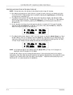
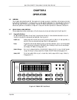
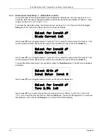
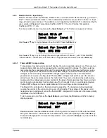
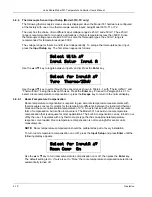
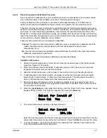
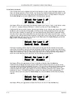
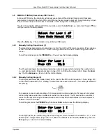
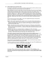
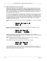
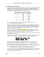
The keypad and display operate on one loop at a time. To toggle display and keypad operation
between loop 1 and loop 2 press the
Loop
key to toggle the display and keypad operation between
Loop 1 and 2. A brief display message indicates which control loop has been selected. You can
determine which loop is active by looking at the heater output display. Loop 1 has “Low,” “Med,” or
“High” in the heater display. Loop 2 has “L2” in the heater display. Also, when you select any of the
following parameters, the active loop number will be displayed: Control Setup, Setpoint, PID/MHP,
Zone Settings, AutoTune, and Heater Range.
Table 4-3. Comparison of Control Loops 1 and 2
Feature Loop
1
Loop 2
(Model 331S Only)
Control Output
Heater Output
Analog Output
Maximum Output Power
50 W
1 W
Output Type
Current Source
Voltage Source
Multiple Output Ranges
Yes
No
Closed Loop PID Control
Yes
Yes
AutoTune Yes
Yes
Zone Tuning
Yes
Yes
Ramping Yes
Yes
Open Loop Control
Yes
Yes
Display in Current or Power
Yes
No
Front Panel Display
Yes
Yes
Setpoint Limit
Yes
Yes
Heater Fault Detection
Yes
No
Bipolar Operation
No
Yes
4-14
Operation

