O & M Manual – Insulated Case ATS Rev: October 2020
Publication Number:
MN0100700E
Version: V10.01.20
Page 13
Once the transfer switch has been mounted to its installation location, perform initial start-up by
following these steps:
1.
Verify No Power from Any Source is Present. (a.k.a.: Utility, Generator or Other Source)
2.
Place the "Control" key switch in the "Disable" position located on the door of the Automatic
Transfer Switch (ATS).
3.
Visually check the position of the operating handle(s) of the "NS" and "ES"
breakers/switches. The handle(s) should be in the down position, indicating both are in
the "Open" position. If they are not, place them in the down position.
4.
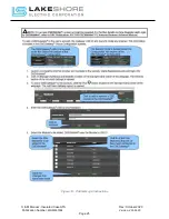
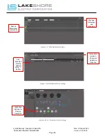
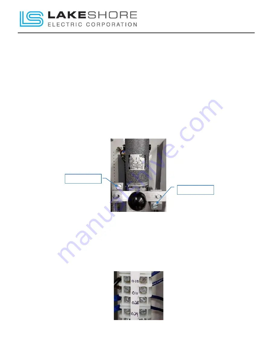
Verify that all the motor slip screws are tight, (2 screws per motor), so that the motor(s) do
not slip when they are powered up in the following sections. See Figure 1 - Motor Slip
Screws for quick location reference.
[These must be checked each time maintenance is performed on the generator or at the
least, yearly.]
Figure 1 - Motor Slip Screws
NOTE: The maximum recommended distance the ATS should be installed from the engine
generator set is 1400 feet, using #10 gage wire for all control wiring.
5.
Control Wire:
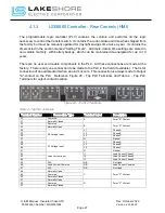
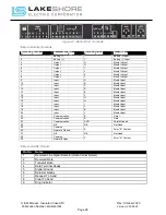
Install the DC control power wires to terminals designated on the specific
units schematic drawing "XXXXXX-03" drawings. (Typical: "010 (negative)" and "011
(positive)". See Figure 2 – Typical Control Wire
subject to change. Please see unit drawings for specifics on current ATS.)
Figure 2 – Typical Control Wire Terminals for a Utility-to-Generator Setup
Slip Screw
Slip Screw


