O & M Manual – Insulated Case ATS Rev: October 2020
Publication Number:
MN0100700E
Version: V10.01.20
Page 50
5.
Operating Mechanism
5.1.
General Information
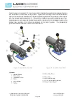
The operating mechanism pictured in Figure 39 - Gear Motor Assembly (page 51), is used in
single motor operated, and dual motor operated transfer switches. The motor (4) is a universal
type, reversible motor and is shipped as a complete component including the gearbox and motor
control board. The gearbox is a sealed unit, which should never require maintenance or attention.
Because of the wide range of molded case switches used on Lake Shore Electric Transfer
Switches, if motor replacement is necessary, please specify the serial number and model number
of the transfer switch.
5.2.
Operation
When a signal to transfer is received from the LSE8600 Controller, the motor is energized, and
the gear box turns the drive drum (8) which sets up a friction pull between itself and the drive shoe
lining (13). This friction pull is enough to pull the drive arms (2) over to the new position, actuating
the switch toggle. As soon as the drive arms have reached their new position, the auxiliary switch
changes position signaling the controller to cut off the motor, while at the same time, setting up
the circuit for the next transfer in the opposite direction. Because of the built-in features of the
friction drive, it is possible to manually operate the switch by moving the manual handle (1) without
engaging any clutches or devices.
5.3.
Required Maintenance
Please refer to the Appendix A, Appendix B and Appendix C for required maintenance on the
operating mechanism necessary to maintain your exclusive one-year Lake Shore Electric
Corporation warranty.
5.4.
Motor Assembly
To assemble the operating mechanism, first place the drive drum keys (11) on each side of the
shaft, which extends from the gearbox. Next, slide the two drive drums (8) on the shafts. Insert
one drive shoe pivot (10) into one drive arm (2) from the bottom, followed by the drive shoe (12)
and the drive shoe lining (13). Be sure that the lining fits snugly into the drive shoe and that the
concave cup end of the drive shoe pivot (10) engages the nipple on the drive shoe. Hold the entire
assembly together and slip it onto one shaft, pushing it all the way to the drive drum. Now the
spring (9) and adjustment screw (3) may be assembled into the drive arm (2) from the top. Repeat
this procedure for the other drive arm assembly if present.

