O & M Manual – Insulated Case ATS Rev: October 2020
Publication Number:
MN0100700E
Version: V10.01.20
Page 51
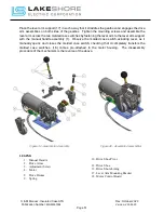
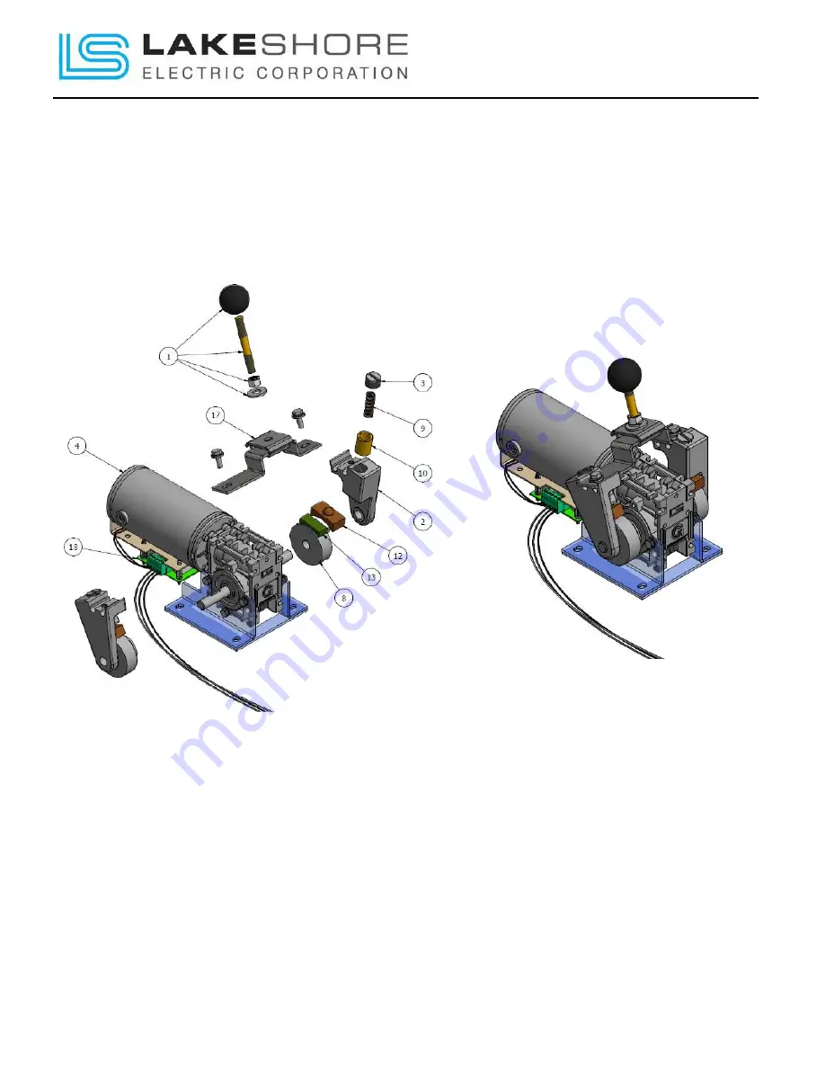
Place the lever arm support (17) in such a way that it straddles the gearbox and engages the drive
arm assemblies on both sides of the gearbox. Tighten the mounting screws and assemble the
lever arm across the two molded case switches by fastening the lever arm to the lever arm support
with the manual handle assembly (1). Observe the molded case switch-actuating lever, as it
manually opens and closes the molded case switch, checking that it completely transfers the
molded case switches. (18) comes pre-attached to the motor housing. The disassembly
procedure of the mechanism is the reverse of the above.
Figure 39 - Gear Motor Assembly
Figure 40 – Assembled Gear Motor
LEGEND
1.
Manual Handle
2.
Drive Arms
3.
Adjustment Screw
4.
Motor
8.
Drive Drums
9.
Spring
10.
Drive Shoe Pivot
12.
Drive Shoe
13.
Drive Shore Lining
17.
Lever Arm Mounting Bracket
18.
Motor Control Board

