O & M Manual – Insulated Case ATS Rev: October 2020
Publication Number:
MN0100700E
Version: V10.01.20
Page 8
1.
Construction
The Transfer Switches covered in this manual use molded case switches and/or circuit breakers
to accomplish the transfer of two separate power sources to a single load.
These molded case circuit breaker(s) and/or switch/switches, (molded case units), are interlocked
via electrical and mechanical control systems.
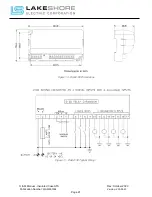
The LSE8600 Controller combined with the auxiliary contact switch located in the molded case
unit encompasses the electrical interlock system.
The physical "Plunger Style" interlock installed between the two molded case units
encompasses the mechanical interlock system. The interlock is located on the rear of the
base plate and is a fulcrum and lever device, which positively prevents both molded case
switches or circuit breakers from being in the ON position simultaneously.
The two control systems provide a redundant interlocking scheme which provides a "Fail-Safe"
design. Note: This mechanical interlock is not provided on units equipped with the Closed
Transition Option.
The gear motors are operated at 120Vac, supplied by the unit. The gear reduction unit is
permanently lubricated so that it requires no maintenance.
All styles of transfer switches are provided with an insulated operating handle to enable personnel
to manually operate the transfer switch in the event of an emergency. The handle is permanently
mounted and readily accessible and allows the operator to manually operate the transfer switch
under load.
All interface relays are of the enclosed industrial type to ensure long life and minimum
maintenance. They are rated for continuous duty to eliminate overheating of coils.
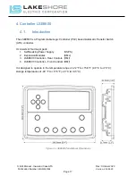
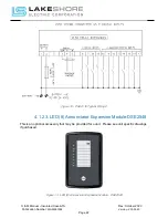
The LSE8600 controller will provide adequate control of the Automatic Transfer Switch (ATS).
These controllers offer programmable timers. Including the plant exerciser, and these values are
stored in non-volatile memory.


