O & M Manual – Insulated Case ATS Rev: October 2020
Publication Number:
MN0100700E
Version: V10.01.20
Page 9
2.
Description of Operation
The following are general descriptions of operation applying to the different styles of Transfer
Switches. Certain accessory additions may modify the sequence of operations as required to
suit specific applications.
2.1.
Single Motor Operator
The Single Motor ATS utilizes a single motor to operate both the normal and emergency molded
case units. Normally, the transfer switch operates on the preferred power source with the Normal
molded case unit in the closed position and the Emergency molded case unit in the open position.
(Refer to Individual Unit Wiring Diagrams Included with the Transfer Switch.)
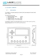
All phases of the preferred power source, S1 (typical: Utility), are continuously monitored by the
voltage sensing inputs of the LSE8600 Controller. These undervoltage settings are preset to 90%
pick-up and 80% drop-out of the nominal voltage. If different settings are required, please contact
Lake Shore Electric for assistance in changing these settings. In the event of a drop in any phase
of the preferred voltage below the dropout set point, the LSE8600 Controller will follow these
steps:
1.
The S1 light on the LSE8600 controller will turn off and the display will indicate a warning
under the "Alarm" screen menu.
2.
The "S2 Start Delay" will time for the Factory Default setting of 3 seconds. This would be
the standard "Engine Generator Start Delay" time to avoid nuisance transfers.
3.
Then the "S1 Return Delay" will time for the Factory Default setting of 3 seconds. This
would be the standard "Time Delay to Emergency" to avoid premature loading of the
generator.
4.
The "NS" molded case unit will open to remove the load from S1 power source, and the
“ES” molded case unit will close at the same time to connect the load to S2 power source.
NOTE: If overvoltage sensing is used, factory default settings would be 120% drop-out and 115%
pick-up of nominal voltage.
The preceding sequence of operation describes the operation of a basic single motor operated,
Automatic Transfer Switch (ATS). Lake Shore Electric offers a wide variety of accessory
equipment to meet customer specifications. Please refer to the schematic diagram provided with
your Lake Shore ATS for specific controls provided.


