background image

Lake Shore Model 642 Electromagnet Power Supply User’s Manual 


Glossary of Terminology 

A-1 

APPENDIX A 


GLOSSARY OF TERMINOLOGY 


accuracy

. The degree of correctness with which a measured value agrees with the true value.

2


electronic accuracy

. The accuracy of an instrument independent of the sensor. 

sensor accuracy

. The accuracy of a temperature sensor and its associated calibration or its ability to match a standard curve. 

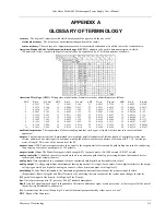
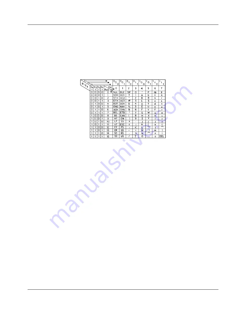
American Standard Code for Information Interchange (ASCII)

. A standard code used in data transmission, in which 

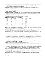
128 numerals, letters, symbols, and special control codes are represented by a 7-bit binary number as follows: 


American Wire Gage (AWG)

. Wiring sizes are defined as diameters in inches and millimeters as follows: 

AWG 

Dia. In. 

Dia. mm 

AWG 

Dia. In. 

Dia. mm 

AWG 

Dia. In. 

Dia. mm 

AWG 

Dia. In. 

Dia. mm 

1  0.2893 7.348 

11 0.0907 2.304 

21 0.0285 0.7230  31 0.0089  0.2268 

2  0.2576 6.544 

12 0.0808 2.053 

22 0.0253 0.6438  32 0.0080  0.2019 

3  0.2294 5.827 

13 0.0720 1.829 

23 0.0226 0.5733  33 0.00708 0.178 

4  0.2043 5.189 

14 0.0641 1.628 

24 0.0207 0.5106  34 0.00630 0.152 

5  0.1819 4.621 

15 0.0571 1.450 

25 0.0179 0.4547  35 0.00561 0.138 

6  0.1620 4.115 

16 0.0508 1.291 

26 0.0159 0.4049  36 0.00500 0.127 

7  0.1443 3.665 

17 0.0453 1.150 

27 0.0142 0.3606  37 0.00445 0.1131 

8  0.1285 3.264 

18 0.0403 1.024 

28 0.0126 0.3211  38 0.00397 0.1007 

9  0.1144 2.906 

19 0.0359 0.9116  29 0.0113 0.2859  39 0.00353 0.08969 

10 0.1019 2.588 

20 0.0338 0.8118  30 0.0100 0.2546  40 0.00314 0.07987 

ambient temperature

. The temperature of the surrounding medium, such as gas or liquid, which comes into contact with the 

apparatus.

1


ampere

. The constant current that, if maintained in two straight parallel conductors of infinite length, of negligible circular cross 

section, and placed one meter apart in a vacuum, would produce between these conductors a force equal to 2 × 10

–7

 newton per 

meter of length.

2

 This is one of the base units of the SI. 

ampere-turn

. A MKS unit of magnetomotive force equal to the magnetomotive force around a path linking one turn of a conducting 

loop carrying a current of one ampere; or 1.26 gilberts. 

ampere/meter (A/m)

. The SI unit for magnetic field strength (H). 1 ampere/meter = 4

π

/1000 oersted 

0.01257 oersted. 

analog controller

. A feedback control system where there is an unbroken path of analog processing between the feedback device 

(sensor) and control actuator (heater). 

analog data

. Data represented in a continuous form, as contrasted with digital data having discrete values.

1


analog output

. A voltage output from an instrument that is proportional to its input. For example, from a digital voltmeter, the output 

voltage is generated by a digital-to-analog converter so it has a discrete number of voltage levels. 

autotuning

. In Lake Shore instruments, the Autotuning algorithm automatically determines the proper settings for Gain 

(Proportional), Reset (Integral), and Rate (Derivative) by observing the time response of the system upon changes in setpoint. 

B

. Symbol for magnetic flux density. 

See

 Magnetic Flux Density. 

bar

. Unit of pressure equal to 10

5

 pascal, or 0.98697 standard atmosphere. 

Baud

. A unit of signaling speed equal to the number of discrete conditions or signal events per second, or the reciprocal of the time of 

the shortest signal element in a character.

2


bit

. A contraction of the term “binary digit”; a unit of information represented by either a zero or a one.

2


BNC

. Bayonet Nut Connector. 

Summary of Contents for 642

Page 1: ...support or relationship whatsoever has existed which in any way affects or mitigates proprietary rights of Lake Shore Cryotronics Inc in these developments Methods and apparatus disclosed herein may b...

Page 2: ...ces do not allow the exclusion of liability for incidental or consequential damages so the above limitation may not apply to you LIMITED WARRANTY STATEMENT Continued 9 EXCEPT TO THE EXTENT ALLOWED BY...

Page 3: ...Lake Shore Model 642 Electromagnet Power Supply User s Manual iii...

Page 4: ...Lake Shore Model 642 Electromagnet Power Supply User s Manual iv This Page Intentionally Left Blank...

Page 5: ...4 3 Operation Under Field Control 2 7 2 4 4 Avoiding Cooling Water Condensation 2 8 3 INSTALLATION 3 1 3 0 GENERAL 3 1 3 1 INSPECTION AND UNPACKING 3 1 3 1 1 Moving and Handling 3 1 3 2 REAR PANEL DE...

Page 6: ...ATER 4 8 4 14 ERROR STATUS DISPLAY 4 8 4 15 EXTERNAL CURRENT PROGRAMMING 4 9 4 16 LOCKING THE KEYPAD 4 9 4 17 COMPUTER INTERFACE 4 10 4 17 1 Changing Serial Baud Rate 4 10 4 17 2 Changing IEEE 488 Int...

Page 7: ...Program Setup 5 16 5 1 5 3 Program Operation 5 20 5 1 6 Troubleshooting 5 20 5 2 SERIAL INTERFACE OVERVIEW 5 21 5 2 1 Changing Baud Rate 5 21 5 2 2 Physical Connection 5 21 5 2 3 Hardware Support 5 22...

Page 8: ...14 7 11 CALIBRATION 7 16 7 11 1 Calibration Interface 7 16 7 11 2 Calibration Equipment 7 17 7 11 3 Calibration Procedure 7 17 7 11 3 1 Calibrate Current Output Zero 7 17 7 11 3 2 Calibrate Current Re...

Page 9: ...ction 3 9 3 13 Output Cable Connection 3 10 3 14 Output Lug Cover Installation 3 10 3 15 Analog Input Output Connector 3 11 3 16 Mounting Hole Pattern 3 12 4 1 Model 642 Power Push Buttons 4 1 4 2 Mod...

Page 10: ...ng of an 8 Bit Register 5 7 5 2 Register Clear Methods 5 7 5 3 Programming Example to Generate an SRQ 5 13 5 4 IEEE 488 Interface Program Control Properties 5 17 5 5 Visual Basic IEEE 488 Interface Pr...

Page 11: ...he Model 642 Linear operation eliminates the radiated radio frequency RF noise associated with switching power supplies allowing the Model 642 to reduce the overall noise in its output and the noise r...

Page 12: ...rrent ramp rate is variable between 0 1 mA s and 99 999 A s To ensure a smooth ramp rate the power supply updates the high resolution DAC 23 7 times per second A low pass filter on the DAC output smoo...

Page 13: ...ccessed using a single key press The keypad can be locked to either lock out all changes or to lock out just the instrument setup parameters allowing the output of the power supply to be changed 1 2 S...

Page 14: ...can be summed with internal current setting Limits Internally clamped at 10 1 V and bandwidth limited at 40 Hz to protect output Connector Shared 15 pin D sub Readings Output current Resolution 0 1 m...

Page 15: ...er Remote enable input TTL low or contact closure to enable output jumper required if unused Valve power output 24 VAC at 1 A maximum automatic or manual control Connector Shared 4 pin detachable term...

Page 16: ...Two 10 mm 0 38 in hose barbs CAUTION Internal condensation can cause damage to the power supply Enclosure type 7 U high 19 in rack mount with integral rack mount ears 25 mm 1 in air space required on...

Page 17: ...pply voltage fluctuations not to exceed 10 of the nominal voltage Power and Ground Connections This instrument must be connected to a dedicated three phase power circuit with proper size of circuit br...

Page 18: ...on cooling water lines inside the power supply can cause severe damage Refer to Section 2 4 4 for additional details Cleaning Do not submerge instrument Clean only with a damp cloth and mild detergen...

Page 19: ...C 417 No 5020 Frame or chassis ground IEC 417 No 5021 Equipotentiality IEC 417 No 5007 On supply IEC 417 No 5008 Off supply IEC 417 No 5172 DOUBLE INSULATION OR REINFORCED Bcakground color yellow Caut...

Page 20: ...Lake Shore Model 642 Electromagnet Power Supply User s Manual 1 10 Introduction This Page Intentionally Left Blank...

Page 21: ...h the Model 642 Power Supply is typically an iron pole twin coil 4 inch pole diameter variable air gap water cooled electromagnet Larger magnets can be used depending on their electrical parameters an...

Page 22: ...ing tested may exhibit changes in their magnetic performance with changes in temperature causing errors in the collected data Typical water connection is shown in Figure 2 2 The magnets may be supplie...

Page 23: ...gn 2 3 POWER LEAD POWER LEAD CROSS CONNECTION WIRING POWER LEAD POWER LEAD CROSS CONNECTION WIRING BOLT BELLEVILLE WASHER CABLE CONNECTION MAGNET POWER LUG PLAIN WASHER NUT PARALLEL WIRING SERIES WIRI...

Page 24: ...RMAL SWITCH FLOW SWITCH WATER VALVE TO 642 MAGNET CONNECTOR VALVE CONTACTS TO 642 MAGNET CONNECTOR FLOW SWITCH CONTACTS INLET OUTLET THERMAL SWITCH Figure 2 4 Typical Thermal Switch Flow Switch and Va...

Page 25: ...provides a higher field The pole faces must be selected to accommodate the size of the sample being tested The air gap is selected based on the size of the sample and the other equipment being used Th...

Page 26: ...Lake Shore Model 642 Electromagnet Power Supply User s Manual 2 6 Magnet System Design Figure 2 5 Typical Curves of Field vs Current for Various Air Gaps and Pole Cap Sizes Sheet 2 of 3...

Page 27: ...peration Under Field Control To obtain a linear field ramp a magnetic sensor such as a Hall probe is placed in the air gap along with the sample being tested The sensor is connected to a Gaussmeter Th...

Page 28: ...15 12 9 6 2 0 29 29 28 27 27 26 24 23 22 21 19 18 16 14 12 10 7 3 0 27 27 26 25 24 23 22 21 19 18 17 15 13 12 10 7 4 2 0 24 24 23 22 21 20 19 18 17 16 14 13 11 9 7 5 2 0 21 21 20 19 18 17 16 15 14 13...

Page 29: ...ies Lake Shore is not responsible for any missing items if not notified within 60 days of shipment Inspect all items for both visible and hidden damage that occurred during shipment If damage is found...

Page 30: ...to connect the optional magnet water valve power and temperature and or flow switch 7 AUXILIARY CONNECTOR An 8 pin detachable screw terminal block is provided to connect the optional Emergency Stop R...

Page 31: ...ety of operators 3 3 1 Line Voltage Selection The Model 642 has four AC line voltage configurations covering seven different input voltages The nominal voltage and voltage tap setting as well as the c...

Page 32: ...inals While holding the locator card in place to keep the wires fully inserted tighten the terminal screws The recommended torque requirement is 0 5 Nm Also tighten the four terminals where the wires...

Page 33: ...ypical cable entry with bushing is shown in Figure 3 5 BUSHING BODY COMPRESSION GROMMET SLIP WASHER COMPRESSION COLLAR CABLE 642 REAR PANEL LOCKING RING CONDUIT BUSHING Figure 3 5 Typical Cable Entry...

Page 34: ...s provided The wiring cover installation is shown in Figure 3 7 Be sure that the voltage indicator tab of the voltage locator card Figure 3 2 shows through the correct indicator slot in the wiring cov...

Page 35: ...densation on the magnet or connecting hoses If the cooling water comes from a facility chiller system condensation is not usually a problem and a control valve is not required In this case it is appro...

Page 36: ...ovided to connect to cooling water The connection to the cooling water source should be made with two 10mm 3 8 in I D fiberglass reinforced hoses and two 20mm 25 32 in adjustable hose clamps In additi...

Page 37: ...ists the current capacity and lead lengths for load connections Lake Shore sells magnet cables in 10 and 20 foot lengths Refer to Paragraph 6 2 for ordering accessories Figure 3 13 shows how the outpu...

Page 38: ...gnet Power Supply User s Manual 3 10 Installation BELLEVILLE WASHER BOLT OUTPUT LUG MAGNET CABLE PLAIN WASHER NUT Figure 3 13 Output Cable Connection LUG COVER 38 mm 1 5 in MOUNTING SCREWS Figure 3 14...

Page 39: ...nce of 50 k The programming voltage is limited internally to approximately 10 1 V Category 1 but care must be taken to insure that maximum current capability of the magnet is never exceeded 3 9 2 Outp...

Page 40: ...ovided on each side for cross ventilation No ventilation panels are required above or below the unit Due to the weight of the power supply it is recommended that the supply be located at the bottom of...

Page 41: ...remote Emergency Stop button or by the Model 642 software when a hazardous fault condition is detected The ON and OFF buttons are illustrated in Figure 4 1 POWER ON BUTTON POWER OFF BUTTON Figure 4 1...

Page 42: ...3 1 Fault LED The Fault LED will light whenever an error condition is encountered It may also be accompanied by an alarm depending on the fault Refer to Table 7 2 Instrument Hardware Errors and Table...

Page 43: ...gram Setup the external current programming mode Refer to Paragraph 4 15 Computer Interface Setup RS 232C and IEEE 488 computer interfaces Refer to Paragraph 4 17 Ramp Segments Setup ramp segment valu...

Page 44: ...her under a single key To skip over a parameter without changing its value press Enter before pressing an arrow or number key To return to the normal display in the middle of a setting sequence press...

Page 45: ...high as 99 999 A s can be entered To change the current ramp rate press the Ramp Rate key The ramp rate value on the normal display will be highlighted to prompt for the new ramp rate value Rate 1 000...

Page 46: ...en the ramp rate field is highlighted use numerical keypad to enter the applicable ramp rate in A s Press Enter to accept the new selection and continue to the next segment Press Escape to restart the...

Page 47: ...value Press Escape to restart the setting sequence and enter a different value Press Escape again to leave the setting sequence NOTE The maximum output current limit value can be set as high as 70 100...

Page 48: ...lve will be energized when the power in the internal power devices exceeds 100 W When the power drops below 100 W the valve will remain energized for an additional minute to remove any residual heat b...

Page 49: ...ss Escape to cancel the new selection and return to the normal display To avoid discontinuities in the output current the external current programming mode cannot be changed if the programming voltage...

Page 50: ...the data entry keys to enter the 3 digit lock code default 123 An asterisk will appear on the display for each number entered If the code entered matches the lock code the display will show Change Acc...

Page 51: ...y to select one of the following terminators CR LF LF CR LF and EOI The default is CR LF Press Enter to accept the new selection and continue to the next setting screen Press Escape to cancel the new...

Page 52: ...p Rate 99 999 A s External Program Mode External Program Mode Internal Ramp Segments Ramp Segments Disabled Ramp Segments Current 0 A Ramp Segments Rate 1 0000 A s Display Brightness 25 Keypad Locking...

Page 53: ...s data onto the bus to other devices A LISTENER receives data from other devices through the bus The BUS CONTROLLER designates to the devices on the bus which function to perform The Model 642 perform...

Page 54: ...ppears as a prompt for the IEEE 488 terminators Computer Interface Select With IEEE Term Cr Lf Use the s or t key to select one of the following terminators CR LF LF CR LF and EOI The default is Cr Lf...

Page 55: ...vice Request Status Byte Register This status register contains important operational information from the unit requesting service The SPD command ends the polling sequence 5 1 3 2 Common Commands Com...

Page 56: ...egister as shown in Figure 5 1 Bits in the event register correspond to various system events and latch when the event occurs When an event bit is set subsequent events corresponding to that bit are i...

Page 57: ...Used 5 Not Not Used 6 Not Used 5 Used 4 Not Used Not 3 Not Used 4 Not Used 3 OSB 7 AND Bit Name 2 1 0 AND Name Bit Name Bit Not Used 2 1 2 1 0 0 ESB 5 MAV 4 3 2 Used 1 Not 0 Bit Name 6 Standard Event...

Page 58: ...T Error Status Condition Register Error Status ERSTR LLV 6 7 5 3 4 7 6 HLV MFF 5 4 3 2 0 1 Name Bit EPE TH CAL 2 1 0 Name Bit Sheet B 1 of 2 To PFF REF PFF REF HLV MFF LLV EPE TH CAL PFF REF HLV MFF L...

Page 59: ...ghted sum of all bits in the register Refer to Table 5 1 The actual commands are described later in this section 5 1 4 1 8 Clearing Registers The methods to clear each register are detailed in Table 5...

Page 60: ...dicate an instrument off on transition Command Error CME Bit 5 This bit is set if a command error has been detected since the last reading This means that the instrument could not interpret the comman...

Page 61: ...ion Condition register The used bits of the Operation Event Register are described as follows Power Limit Bit 2 This bit is set if the output is in power limit Ramp Done Bit 1 This bit is set when the...

Page 62: ...Status Event Register are described as follows Temperature Fault TF Bit 4 This bit is set if the internal temperature of the instrument exceeded the maximum safe value of 45 C The instrument will shut...

Page 63: ...if a fault condition is detected on the magnet flow switch interlock High Line Voltage HLV Bit 4 This bit is set if the power line voltage exceeds an acceptable amplitude Operation can continue but ad...

Page 64: ...low to high the Service Request hardware line on the bus is set this is the RQS function of the bit See Paragraph 5 1 4 4 3 In addition the status of the bit may be read with the STB query which retur...

Page 65: ...t clear MSS The MSS bit stays set until all enabled Status Byte summary bits are cleared typically by a query of the associated event register refer to Paragraph 5 1 4 4 4 The programming example in T...

Page 66: ...sed when it is important to prevent any additional communication on the bus during a pending operation 5 1 5 IEEE 488 Interface Example Programs A Visual Basic program is included to illustrate the IE...

Page 67: ...Lake Shore Model 642 Electromagnet Power Supply User s Manual Computer Interface Operation 5 15 Figure 5 7 GPIB0 Setting Configuration Figure 5 8 DEV 12 Device Template Configuration...

Page 68: ...IEEE 488 Interface Program in Visual Basic 1 Start VB6 2 Choose Standard EXE and select Open 3 Resize form window to desired size 4 On the Project Menu select Add Module select the Existing tab then n...

Page 69: ...the Code Editor window under the Object dropdown list select General Add the statement Public gSend as Boolean b Double Click on cmdSend Add code segment under Private Sub cmdSend_Click as shown in T...

Page 70: ...ntil gSend True Loop until Send button pressed gSend False Set Flag as False strCommand frmIEEE txtCommand Text Get Command strReturn Clear response display strCommand UCase strCommand Set all charact...

Page 71: ...dentify the board or device on the GPIB Valid primary addresses range from 0 to 30 00H to 1EH Adding 32 to the primary address forms the Listen Address LA Adding 64 to the primary address forms the Ta...

Page 72: ...rrectly spelled query without a nothing will be returned Incorrectly spelled commands and queries are ignored Commands and queries should have a space separating the command and associated parameters...

Page 73: ...st for connecting the instrument to computers with either 9 or 25 pin connectors Paragraph 7 10 5 gives the most common pin assignments for 9 and 25 pin connectors Please note that not all pins or fun...

Page 74: ...is a method of error detection One parity bit configured for odd parity is included in each character ASCII letter and number characters are used most often as character data Punctuation characters ar...

Page 75: ...guarantee timing between messages All of this is the responsibility of the user program When issuing commands only the user program should Properly format and transmit the command including terminato...

Page 76: ...ow to desired size 4 On the Project Menu click Components to bring up a list of additional controls available in VB6 5 Scroll through the controls and select Microsoft Comm Control 6 0 Select OK In th...

Page 77: ...statement Public gSend as Boolean b Double Click on cmdSend Add code segment under Private Sub cmdSend_Click as shown in Table 5 8 c In the Code Editor window under the Object dropdown list select Fo...

Page 78: ...her events Loop Until gSend True Loop until Send button pressed gSend False Set Flag as false strCommand frmSerial txtCommand Text Get Command strReturn Clear response display strCommand UCase strComm...

Page 79: ...sing either IEEE 488 Interface program If you enter a correctly spelled query without a nothing will be returned Incorrectly spelled commands and queries are ignored Commands and queries should have a...

Page 80: ...at nn nnnn current Specifies the output current setting 0 0000 70 1000A Remarks Sets the current value that the output will ramp to at the present ramp rate Setting value is limited by LIMIT Sample Qu...

Page 81: ...er Cmd 32 RDGI Current Output Reading Query 35 DISP Display Parameter Query 32 RDGV Output Voltage Reading Query 36 ERCL Error Clear Cmd 32 RSEG Ramp Segments Enable Cmd 36 ERST Error Status Query 32...

Page 82: ...Serial number firmware version Instrument firmware version main firmware DAC firmware Example LSCI MODEL642 1234567 1 0 1 0 OPC Operation Complete Command Input OPC term Remarks Used in conjunction wi...

Page 83: ...ption STB Status Byte Query Input STB term Returned bit weighting term Format nnn Remarks This command is similar to a Serial Poll except it is processed like any other instrument command It returns t...

Page 84: ...ph 5 1 4 3 for a list of error bits ERST Error Status Query Input ERST term Returned hardware errors operational errors term Format nnn nnn Remarks The integers returned represent the sum of the bit w...

Page 85: ...address 1 30 Address 0 and 31 are reserved Example IEEE 0 0 4 term After receipt of the current terminator the instrument uses CR LF as the new terminator uses EOI mode and responds to address 4 IEEE...

Page 86: ...ts code Specifies lock out code Valid entries are 000 999 Remarks Locks out all front panel entries operations Example LOCK 1 123 term Enables keypad lock and sets the code to 123 LOCK Keypad Lock Que...

Page 87: ...y Input OPSTE term Returned bit weighting term Format nnn Refer to Paragraph 5 1 4 2 2 for a list of operational status bits OPSTR Operational Status Register Query Input OPSTR term Returned bit weigh...

Page 88: ...n term segment Specifies the ramp segment to be modified 1 5 current Specifies the upper output current setting that will use this segment 0 0000 70 1000A rate Specifies the rate at which the current...

Page 89: ...ending the command To restart the ramp use the SETI command to set a new output current setpoint XPGM External Program Mode Command Input XPGM mode term Format n mode 0 Internal 1 External 2 Sum Examp...

Page 90: ...Lake Shore Model 642 Electromagnet Power Supply User s Manual 5 38 Computer Interface Operation This Page Intentionally Left Blank...

Page 91: ...wo rear handles 6051 Terminal Block 4 Pin 6052 Terminal Block 8 Pin 6252 15 pin D sub mating connector analog I O 108 654 Strain Relief Bushing Kit Calibration Certificate 6 2 ACCESSORIES AVAILABLE Pa...

Page 92: ...Lake Shore Model 642 Electromagnet Power Supply User s Manual 6 2 Options and Accessories This Page Intentionally Left Blank...

Page 93: ...2243 ext 131 Sales Instrument Service Fax 614 818 1600 614 818 1609 Sales Instrument Service When contacting Lake Shore please provide your name and complete contact information including e mail addr...

Page 94: ...avoid potentially lethal shocks turn off the power supply and disconnect it from AC power before performing this procedure 1 Identify the power wiring access panel on the rear of the Model 642 2 Turn...

Page 95: ...ap Circuit Breaker 200 V 204 V 18 A 208 V 204 V 18 A 220 V 225 V 17 A 230 V 225 V 17 A 380 V 380 V 12 A 400 V 408 V 12 A 415 V 408 V 12 A WARNING To avoid potentially lethal shocks turn off the power...

Page 96: ...expected to clear and prevent operation of the Model 642 Proper voltage selection must be made before connection to the power mains Access to these fuses is through the power wiring access panel WARNI...

Page 97: ...r Errors are related to user requests that cannot be processed These errors generate responses that immediately explain the cause of the error These are usually simple order of operation issues and ar...

Page 98: ...water temperature External Current Program Error The instrument was not allowed to change to external or sum current programming modes including power up because the programming voltage was greater t...

Page 99: ...edure Only qualified personnel should perform this procedure 7 8 1 Removal 1 Set power switch to Off O and disconnect power cord from the power outlet 2 Remove the Model 642 from rack if necessary to...

Page 100: ...ESDS devices Wear shock proof wrist straps resistor limited to 5 mA to prevent injury to service personnel and to avoid inducing an Electrostatic Discharge ESD into the device 13 Use IC puller to remo...

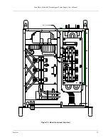
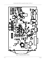
Page 101: ...Lake Shore Model 642 Electromagnet Power Supply User s Manual Service 7 9 DIGITAL BOARD Figure 7 5 Board Locations top view...

Page 102: ...C97 C96 C106 C98 U37 U51 R70 TEST C112 RUN JMP1 C109 R54 R53 C23 U9 R41 U21 C54 U26 R8 R11 R10 J4 GND2 U2 KEYPAD PCB R5 R7 U7 R6 C7 TP2 C10 C3 R14 R12 C44 VRDG R33 R9 U10 R27 C18 R16 U14 R44 C32 U22...

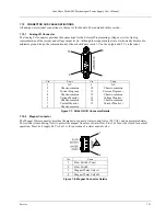
Page 103: ...1 8 9 15 Pin Name Pin Name 1 2 3 4 5 6 7 8 NC Chassis common Current Program Chassis common Voltage Monitor Chassis common Current Monitor Chassis common 9 10 11 12 13 14 15 NC Chassis common Current...

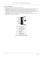
Page 104: ...an be used to communicate the presence of a Model 642 fault to external equipment The relay follows the operation of the Fault light on the front panel Both normally open and normally closed configura...

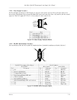
Page 105: ...Figure 7 10 Power Supply Connector Details 7 10 5 RS 232C Serial Interface Connector This connector provides one of two means of computer interface Command descriptions are found in Section 5 9 6 5 1...

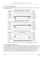
Page 106: ...5 GND 2 RD in 3 TD out 3 TD out 2 RD in 1 NC out 4 DTR 6 DSR in 1 DCD in 4 DTR out 6 DSR in 7 DTR tied to 4 8 CTS in 8 NC 7 RTS out 9 NC 9 NC NOTE Same as null modem cable design except PC CTS is prov...

Page 107: ...ine 2 Data Input Output Line 3 Data Input Output Line 4 End Or Identify Data Valid Not Ready For Data Not Data Accepted Interface Clear Service Request Attention Cable Shield Data Input Output Line 5...

Page 108: ...ts using the CALZ and CALG interface queries before attempting to calibrate This will give the operator experience with the interface command data formatting and typical values If the old values are s...

Page 109: ...DVM The voltmeter must measure VDC accurately to 10 s of V if resolution to 10 s of mA from the Model 642 The Agilent Model 34401 DMM or better is suggested 7 11 3 Calibration Procedure The following...

Page 110: ...this calibration to non volatile memory 7 11 3 5 Calibrate Output Current Gain Span This calibration is the most difficult and most important of the procedure It first requires measuring the span of t...

Page 111: ...t to 0 28 Set the Model 642 output current to 0 A 29 Calculate the gain constant per the following equation Current Output Gain Constant 200 Imax Imin 130 Imaxpostrim Iminpostrim Imaxnegtrim Iminnegtr...

Page 112: ...dpos 0 010 A 16 Set the Model 642 output current to 0 A 17 Send CALSAVE to write this calibration to non volatile memory This method is somewhat lengthy but averages the differences between positive a...

Page 113: ...he reading needed for this step 4 Measure the voltage directly across the 9 V battery and record Vmeasured 5 Calculate the gain constant per the following equation Programming Voltage Reading Gain Con...

Page 114: ...e value term Format nn nnnnnnn type Specifies the item to calibrate Valid entries are 0 Output I Reading 1 Bias A Reading 2 Bias B Reading 3 Gnd Diff Reading 4 Out Con Reading 5 Output V Reading 6 Boo...

Page 115: ...paratus 1 ampere The constant current that if maintained in two straight parallel conductors of infinite length of negligible circular cross section and placed one meter apart in a vacuum would produc...

Page 116: ...ple This returned flux tends to decrease the net magnetic field strength internal to the sample yielding a true internal field Hint given by Hint Ha DM where M is the volume magnetization and D is the...

Page 117: ...al and an external magnetic field applied at right angles to the current Named for Edwin H Hall 1855 1938 an American physicist hertz Hz A unit of frequency equal to one cycle per second hysteresis Th...

Page 118: ...roperties A small highly magnetic sample can have exactly the same moment as a larger weakly magnetic sample see Magnetization Measured in SI units as A m2 and in cgs units as emu 1 emu 10 3 A m2 magn...

Page 119: ...rely mounted in an instrument rack The standard rack mount is 19 inches wide A full rack instrument requires the entire width of the rack Two half rack instruments fit horizontally in one rack width r...

Page 120: ...water Freezing point of water Absolute zero kelvin Celsius Fahrenheit 0 K 273 15 K 373 15 K 273 15 C 0 C 100 C 459 67 F 32 F 212 F Triple point of water 273 16 K To convert Kelvin to Celsius subtract...

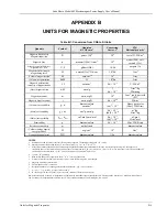
Page 121: ...Volume energy density energy productk W erg cm3 10 1 J m3 Demagnetization factor D N dimensionless 1 4 dimensionless NOTES a Gaussian units and cgs emu are the same for magnetic properties The definin...

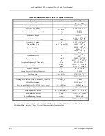
Page 122: ...Wb 4 1357 10 15 J Hz 1 C 1 Josephson Frequency Voltage Ratio 2e h 483 5939 THz V 1 Quantum of Circulation h 2me h me 3 6369 10 4 J Hz 1 kg 1 7 2739 10 4 J Hz 1 C 1 Rydberg Constant R 1 0974 107 m 1 Pr...

Reviews: