Lake Shore Model 642 Electromagnet Power Supply User’s Manual
2-4
Magnet System Design
2.3.3
Temperature Switches and Flow Switches
As discussed in Section 2.3.1, water-cooling for the magnet is essential. To protect the magnet from damage resulting
from an interruption in cooling water, a flow switch, temperature switches or both should be installed. The switches must
have a normally closed contact, and if multiple switches are used, they must be connected in series. The switches are
then connected to the Flow Switch terminals of the Magnet Connector on the Model 642. The Model 642 monitors the
switches and if an open is detected, the output current is ramped to zero. (Flow switch monitoring depends on water
valve mode setting. See sections 4.12 and 4.13 for details.)Given the cost of the magnet, it is prudent to use both
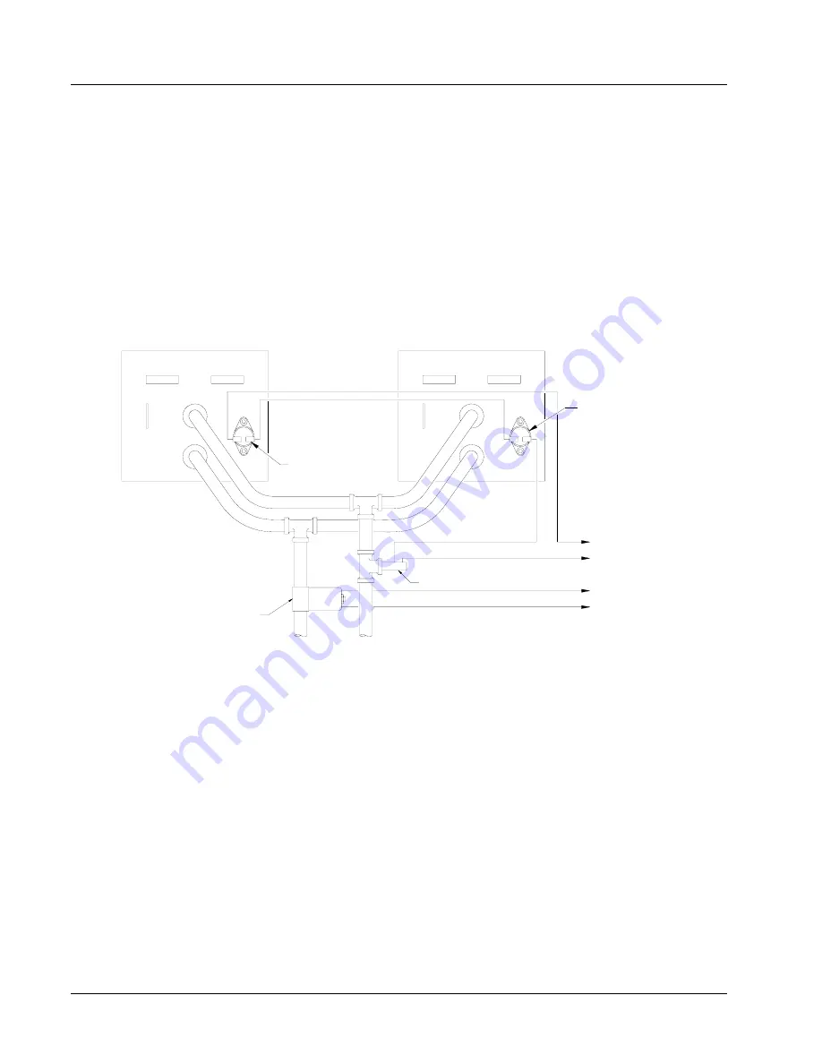
temperature and flow switches. Some installations use two flow switches, one in the exhaust line of each coil so that if a
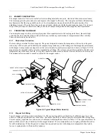
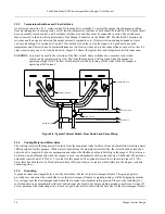
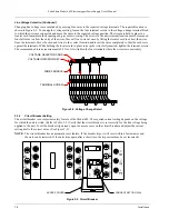
clog occurs in only one coil, it can be detected. Figure 2-4 shows the typical flow and temperature switch connection.
CAUTION:
Care must be used in the selection of the flow switch. Some switches use a sensitive reed switch,
which can be overpowered by stray flux from the magnet and will not open when the magnet is
operating at high field. The flow switch must be tested by turning off the water while the magnet is
operating at full current.
THERMAL SWITCH
FLOW SWITCH
WATER VALVE
TO 642 MAGNET CONNECTOR VALVE CONTACTS
TO 642 MAGNET CONNECTOR FLOW SWITCH CONTACTS
INLET
OUTLET
THERMAL SWITCH
Figure 2-4. Typical Thermal Switch, Flow Switch and Valve Wiring
2.3.4
Cooling Water and Water Valve
The cooling water for the magnet can be drawn from the municipal water facility or from a dedicated re-circulating water
chiller designed for this purpose. When water is drawn from the municipal water facility, the water should be turned on
only when it is required to reduce consumption and reduce the likelihood of scale build-up in the magnet. The water can
be turned on and off manually when the magnet is used, or automatically with a solenoid valve. The Model 642 provides
automatic control and a 24 VAC at 1 A output for this purpose. The optional water valve is shown in Figure 2-2. The
water inlet line should also be fitted with a sediment filter (not shown) to reduce scale build-up in the magnet coils and
connecting lines.
2.3.5 Grounding
A ground connection (tapped hole) is usually available at the rear of the electromagnet frame. This ground point is
provided for customers who would like to use the electromagnet frame as a signal ground or will be bringing hazardous
live voltages near the electromagnet and would like to make it an electrical safety ground. Please verify suitability for
such a function and compatibility with local and national electrical codes before making ground connections. Scrape off
excess paint near the connecting screw to ensure a good electrical contact with the bare steel of the electromagnet frame.

