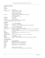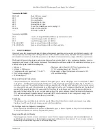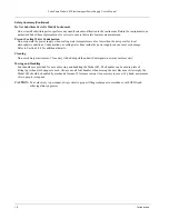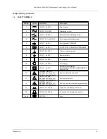
Lake Shore Model 642 Electromagnet Power Supply User’s Manual
3-2
Installation
3.2 REAR
PANEL
DEFINITION
This paragraph defines the rear panel of the Model 642. Refer to Table 3-1. Readers are referred to paragraphs that
contain installation instructions and connector pin-outs for each feature.
CAUTION:
Verify that the Model 642 has been set up for the proper line voltages.
CAUTION:
Make rear panel connections with the instrument power off.
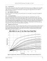
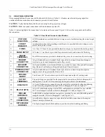
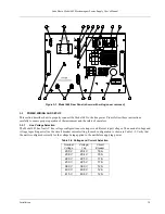
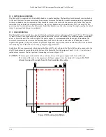
Table 3-1 below highlights the connections to be made on the rear panel. Figure 3-1 shows the rear panel and identifies
the connectors.
Table 3-1. Rear Panel Connector Identification
1
VOLTAGE
SELECTION
16 DIN terminals are provided behind a wiring cover to facilitate setting the correct input
voltage.
2
CIRCUIT
BREAKER
An adjustable current auto-resetting circuit breaker is provided behind a wiring cover to
protect main power circuits.
3
FUSES
¼ A Class CC fuses (2) are provided behind a wiring cover to protect the start-up circuit.
4
CABLE ENTRY
A 34 mm (1.3 inch) hole is provided for power cable entry and strain relief bushing.
5
POWER
TERMINALS
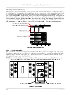
Four DIN terminals are provided behind a wiring cover for connection of power wiring.
6
MAGNET
CONNECTOR
A 4-pin detachable screw terminal block is provided to connect the optional magnet
water valve power and temperature and/or flow switch.
7
AUXILIARY
CONNECTOR
An 8-pin detachable screw terminal block is provided to connect the optional Emergency
Stop, Remote Fault Indicator, Remote Enable and Chassis Ground.
8
POWER SUPPLY
CONNECTOR
A 4-pin detachable screw terminal block is provided to connect the optional power
supply water valve power and/or flow switch.
9
COOLING
WATER
Two 10 mm (3/8”) hose barbs are provided for input and output of cooling water.
10
OUTPUT
TERMINALS
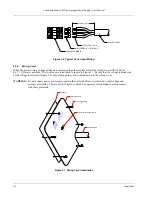
Two output lugs are provided for the magnet cable connections. Refer to Paragraph 3.8
and Figures 3-13 and 3-14 for connecting the magnet cables to the instrument.
11
ANALOG I/O
A 15-pin D subminiature connector provides output for current and voltage monitoring,
as well as analog programming input. Refer to Paragraph 3.9 and see Figure 7-7.
12
RS-232C (DTE)
A 9-pin D subminiature plug wired in DTE configuration is provided for use with RS-
232C serial computer interface. Refer to Paragraph 5.2.2 and see Figure 7-11.
13
IEEE-488
INTERFACE
An IEEE-488 compliant interface connector is provided for use with IEEE-488 parallel
computer interface. Refer to Paragraph 5.1 and Figure 7-12.
14
CHASSIS
CONNECTION
An earth safety chassis connection is provided to facilitate connection to the magnet
frame if noise problems exist.
15
DETACHABLE
HANDLES
Two high-strength detachable handles are provided to aid in handling and lifting.

