Lake Shore Model 642 Electromagnet Power Supply User’s Manual
Service
7-5
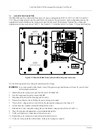
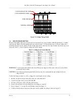
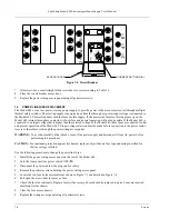
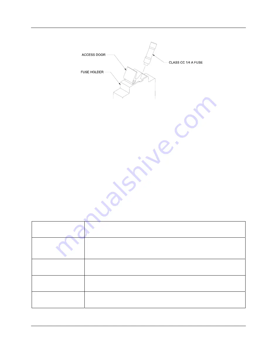
Figure 7-4. Fuse Holder Detail
7.6 ERROR
MESSAGES
The following messages appear on the lower part of the instrument display when it identifies a problem during operation.
The Fault LED will light in conjunction with the error message. A more extensive description of the error message can
shown by pressing the
Status
key. If the error condition can be immediately cleared, it can be done by pressing the
Status
key while in the error status display. Refer to Paragraph 4.14 for a description of the error status display.
Error messages are divided into three groups:
Instrument Hardware Errors
are related to internal instrument circuitry. When one of these errors occurs, the Fault
LED is solidly lit, the output setting is set to 0 A, current entry will not be allowed and there is no way to clear the
error unless power is cycled. If one of these error messages persists after power is cycled, the instrument requires
repair. Instrument Hardware Errors are listed in Table 7-2.
Operational Errors
are related to instrument operation and do not necessarily indicate a hardware problem. When one
of theses errors occurs, the Fault LED will be blinking and the error condition can be cleared once the fault condition
has been removed. Operational Errors are listed in Table 7-3.
User Errors
are related to user requests that cannot be processed. These errors generate responses that immediately
explain the cause of the error. These are usually simple order-of-operation issues and are easily resolved. The fault
LED is not used for these simpler errors. User Errors are self-explanatory and are therefore not listed.
Table 7-2. Instrument Hardware Errors
Internal Temperature Fault
Cold Plate temperature is over 45° C. The output setting is set to 0 A and no current
entry will be allowed. The error message will flash for 10 seconds then the Model 642
will turn itself off.
Output Over Voltage
The output voltage is greater than the 44 V compliance voltage limit indicating a
problem with the compliance voltage circuitry. The output setting is set to 0 A and no
current entry will be allowed. The error message will flash for 10 seconds then the
Model 642 will turn itself off.
Output Over Current
The measured output current exceeded 73 A. The output setting is set to 0 A and no
current entry will be allowed. The error message will flash for 10 seconds then the
Model 642 will turn itself off.
DAC Processor not
Responding
The processor that controls the output DAC is not responding or is responding
incorrectly. The output setting is set to 0 A and no current entry will be allowed.
Cycle power to attempt to clear.
Output Control Failure
One of the internally monitored voltages is beyond an acceptable range on power up.
The output setting is set to 0 A and no current entry will be allowed. Cycle power to
clear attempt to clear.

