background image


2

INTRODUCTION 
W

elcome to the 

Ergo-One

®

 Plus Power Tug

...a member of Lakeside Manufacturing’s family of 

quality material handling products.  We know you'll be depending on the TUG, so we have taken great 
care to make it completely reliable.  This Owner's Manual is designed to help you get the most out of 
your 

Ergo-One

®

 Plus Power Tug

 and includes very important safety and care information.  Please read 

it thoroughly and keep it handy for reference.  Thank you for choosing the 

Ergo-One

®

 Plus Power Tug


Information in this manual is based upon specifications in effect at the time of publication.  Lakeside 
reserves the right to make changes at any time without notice.  Lakeside products are covered by patents, 
patents pending, and other rights reserved. 


Be sure to complete the Owner's Information box on the front cover.  This will be your record of 
important information which will help you if your 

Ergo-One

®

 Plus Power Tug

 ever requires service.  

When seeking repair parts while your 

Ergo-One

®

 Plus Power Tug

 is under warranty, a copy of your bill 

of sale may be requested to verify warranty status. 


FAILURE TO READ THIS OWNER'S MANUAL WILL VOID THE WARRANTY. 


If there is anything in this manual that you do not understand or that you are unsure of, DO NOT 
OPERATE your Ergo-One

®

 Plus Power Tug.  Call our Customer Service Hotline at: 


800-558-8565


Summary of Contents for Ergo-One Plus 8162

Page 1: ...ual Lakeside Manufacturing Inc 4900 W Electric Avenue West Milwaukee WI 53219 Lakeside products are protected by patents patents pending and other rights reserved Toll free 800 558 8565 Fax 414 902 6446 Visit us on line at eLakeside com 040909 TABLE OF CONTENTS ...

Page 2: ...5 6 TOWING WITH THE Ergo One Plus Power Tug 7 BATTERIES 8 BATTERY LIFE 8 BATTERY LOAD TESTING 8 CIRCUIT BREAKER FUSES 9 MAINTENANCE 9 MAINTENANCE SCHEDULE 9 MAINTENANCE PROCEDURES 9 TROUBLE SHOOTING CHECKLIST 10 PUSHING MANUALLY MODIFYING EXISTING CARTS FOR TOWING WARRANTY 10 11 15 Ergo One Plus Power Tug PRODUCT SERVICE INFORMATION please fill out and keep this manual on hand for service records ...

Page 3: ... the time of publication Lakeside reserves the right to make changes at any time without notice Lakeside products are covered by patents patents pending and other rights reserved Be sure to complete the Owner s Information box on the front cover This will be your record of important information which will help you if your Ergo One Plus Power Tug ever requires service When seeking repair parts whil...

Page 4: ...go One Plus Power Tug 12 Always detach the Ergo One Plus Power Tug before connecting towed carts or loading or unloading carts 13 Always load the towed carts evenly distributing the load to prevent tipping 14 Always take corners slowly and with caution to prevent the load from shifting 15 Do not use the Ergo One Plus Power Tug to push or pull stationary objects 16 Always unplug the batteries befor...

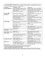
Page 5: ...or injury if the maximum speed is not limited Direction of Motion Direction of motion is controlled by the finger control lever located to the right and left sides of the center section of the hand control unit Rotating the top of the lever away from you accelerates the cart away from you Rotating the bottom of the lever accelerates the cart towards you To STOP release the control lever Let the ca...

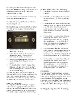
Page 6: ... the faster it will go To Drive the Ergo One Plus Power Tug 1 Turn the key switch clockwise to the Drive Position 2 Select the speed range by depressing either the rabbit or turtle side of the speed range switch 3 For the cart to travel away from you gently rotate the top of the control lever away from you The cart will start to move and accelerate away from you to the desired speed proportional t...

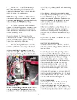
Page 7: ...ate and remove the four finger turn screws that secure the plastic shroud to the frame 5 Gently lift the shroud up and forward carefully feeding the charging cord through the shroud The shroud is still attached to the wiring harness 6 Locate the Battery Indicator wiring harness located below the Battery Discharge Indicator on the shroud 7 Disconnect the wiring harness at its connecter 8 Place the ...

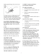
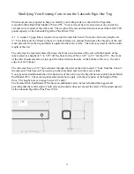
Page 8: ... not disengage when the handle is pushed forward The more weight transferred on to the tug the harder it is to steer Note The Tug s tiller will slowly come towards the operator as the receiver grips the pin STOP pushing on the Up Arrow when the cart s wheels lift slightly off the ground or when the actuator stalls 5 With the cart attached to the Tug careful driving operation can resume Remember th...

Page 9: ...up you may need to replace the batteries Heating or swelling of the batteries sometimes accompanied by an acrid odor is another sign that the batteries may require replacement Other factors which can reduce battery life are irregular or inefficient charging leaving the batteries in a discharged state for a prolonged period of time extreme temperatures and cargo weight If you notice any of these co...

Page 10: ...r Ergo One Plus Power Tug often you will find it to your advantage to perform this maintenance more frequently CAUTION Turn the cart off before performing any maintenance Every Day or As Needed 1 Maintain the batteries charge 2 Clean debris from the wheels and drive unit assembly 3 Inspect tow hitch assemblies installed on towed carts Once Each Month 1 Check for loose connectors and any signs of u...

Page 11: ...tteries Fully charge batteries Load test batteries Motor worn out Contact Authorized Service Center Unit Runs but Actuator Won t Move Blown Fuse Check and replace fuse Bent Actuator Check Actuator Replace Actuator Battery Weak or Won t Take a Charge Battery charge low Fully charge and load test batteries Replace if bad Charger power interrupted Look at charger indicator lights for indication that ...

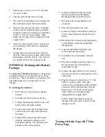
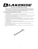
Page 12: ...d between the front swivel casters of the cart with the bottom of the tube located at a height of 5 to 5 25 off the floor for the 4750 or 6 25 to 6 5 for the 4755 The front of the tube should extend to or just past the forward most structure of the bottom of the cart the cart s edge or cart s bumper The tube must have a 332 hole centered through the sides of the tube located 1 back from the front ...

Page 13: ... tube on to the cart to make sure that there are no obstructions under the cart that would interfere with the tube when installed If there are no problems proceed 4 Drop the tube down and clean the surface areas on the cart with alcohol where the grip adhesive will contact 5 Remove the adhesive protection tape from both of the tube grips 6 Center the tube s grip ends to both sides of the cart and ...

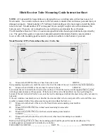
Page 14: ...alation B Measure the LENGTH of the cart base from front to back LENGTH ______________ Look under the cart to identify the lowest points on the cart Mark the location on the supplied drawing along with the ground clearance of those points If the bottom of the cart is flat and there is a clear path along the bottom of the cart for the hitch tube to run note that on the drawing and submit this sheet...

Page 15: ...art and align with the taped marks 5 Fit the tube on to the cart to make sure that there are no obstructions under the cart that would interfere with the tube when installed If there are no problems proceed 6 Drop the tube down and clean the surface areas on the cart with alcohol where the grip adhesive will contact 7 Remove the adhesive protection tape from both of the tube grips 8 Center the tub...

Page 16: ...n and is limited to the repair or replacement of components covered under the parts warranty Failure of any part or system caused by abuse or vandalism voids this entire Warranty Service calls trip charges transportation to or from the service center or distributor or other charges imposed by the distributor or service center to make the repairs on the product Defects product or part failure cause...

Reviews: