background image


II. 

WARRANTY 


All products manufactured and marketed by this corporation are warranted to be 

free of defects in material and workmanship for a period of at least one-year from 

the date of delivery. Extended warranty or no coverage applies as follows: 


**All LAKOS separators---five year warranty 

**Pump seals are not covered under warranty 


All other components and coatings: 12 months from the date of installation; if 

installed 6 month or more after ship date, warranty shall be a maximum of 18 

months from ship date. 


If a fault develops, notify us or your local representative, giving a complete 

description of the alleged malfunction. Include the model numbers(s), date of 

delivery and operating conditions of subject products(s). We will subsequently 

review this information and, at our option, supply you with either servicing data or 

shipping instructions with returned materials authorization number. Upon prepaid 

receipt of subject product(s) at the instructed destination, we will perform such 

necessary product repairs or replace such product(s) at our expense. 

This limited warranty does not cover any products, damages or injuries resulting 

from misuse, misapplication, neglect, normal expected wear, chemically-caused 

corrosion, improper installation or operation contrary to factory recommendation. 

Nor does it cover equipment that has been modified, tampered with or altered 

without authorization. 


No other extended liabilities are stated or implied and this warranty in no event 

covers incidental or consequential damages, injuries or cost resulting from any such 

defective products(s). 


This warranty supersedes any and all previous warranties provided by LAKOS 

Filtration Solutions. 


III. 

DELIVERY INSPECTION OF STS SERIES MEDIA FILTERS 


1. 

Immediately inspect the system upon arrival for any damage that may have 

occurred during shipping. Look for crate damage, pierced or torn boxes or 

any other signs of handling, which may suggest damage to the system. 


2. 

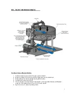
LAKOS STS Series Media Filters are shipped with all major components 

assembled onto the skid. Selected small items, such as the pressure 

gauges, may be removed and inserted into the control box for shipping. 


Summary of Contents for STS Series

Page 1: ...FRESNO CALIFORNIA USA LS 644E Rev 12 20 Installation and Operators Manual Model Tower System Media Filters STS ...

Page 2: ...ump see drawing STS 0001 or by tapping directly to a basin or remote sump to achieve a given turnover rate Please note that all standard STS system pumps require flooded suction for proper operation Please contact the factory if you have a installation that will require the pump tolift water LAKOS does not recommend using the standard STS Series Media Filters for basin remote sump sweeping applica...

Page 3: ...rform such necessary product repairs or replace such product s at our expense This limited warranty does not cover any products damages or injuries resulting from misuse misapplication neglect normal expected wear chemically caused corrosion improper installation or operation contrary to factory recommendation Nor does it cover equipment that has been modified tampered with or altered without auth...

Page 4: ...hooks or straps attached to system piping or manifold as damage could occur to the system Anchor the unit to the foundation to prevent vibration and or movement 2 All STS systems required flooded pump suction for proper operation Please make sure that all inlet piping to the system is located to ensure that the pump is flooded with water at all times If you system is equipped with a self priming p...

Page 5: ...control backwash flow Check local codes to determine if appropriate backflow prevention is necessary on the backwash line 8 Determine if the drain for the backwash can handle the necessary backwash flow see backwash flow chart below All LAKOS STS Media Filters are factory set to backwash for 3 minutes If the drain can not handle the total backwash flow LAKOS does offer backwash holding tanks that ...

Page 6: ...the sand be added slowly so that no damage occurs to the laterals on the underdrain assembly Spread the sand level within the tank then close and secure the access port 11 Remove pressure gauges from packaging and install at the street tee connections on the inlet manifold elbow and tank outlet elbow 12 Double check the controller settings Factory settings should be as follows Pressure differentia...

Page 7: ...ed to top and is uniformly dispersed over the media bed 3 Water passes thru the media bed leaving debris behind 4 Filtered water exits the OUTLET 5 The media bed is cleaned through a backwash cycle at specified intervals or differential pressure The backwash cycle runs for a 3 minute period 6 System returns to normal operating mode 7 ...

Page 8: ...oosters are in use 1 Make sure that there is water in the main inlet line to provide flooded suction to the STS system pump DO NOT DRY RUN THE PUMP All pumps require a wet primed suction before starting using water as a lubricant for their seals John Crane type seals e g Silicon Carbide Seals can wear out in 20 seconds of dry operation It only takes a small amount of water to lubricate the seal an...

Page 9: ...using an STS SWP system 7 BACKWASHING Differential pressure across the filter media progressively increases as trapped particulate accumulate in the filter media bed On filter equipped with automatic backwash the backwash cycle is initiated upon reaching a 10 psig pressure differential Since units with automatic controls perform this function as necessary a detailed backwash procedure is only prov...

Page 10: ...tor from the plumbing entirely Store them indoors in a warm and dry place The STS tank and the purge line should also be drained of liquid to prevent damage from freezing To remove trapped water from the separator use a compressed air hose directed into the acceptance chamber Alternatively flush system withantifreeze Heat tracing or pipe insulation may be used Please contact your local supplier of...

Page 11: ...tlet These are not provided as a standard option by Lakos but are available if a valve kit is ordered Loosen the nuts or threaded stud and remove the lid Remove the basket and clean Inspect the O ring or gasket and if damaged replace Replace the lid and tighten the nuts B PUMP AND MOTOR Make sure that there are no leaks in the pump housing If leaks occur at the back of the volute casing you may ha...

Page 12: ...hanical interference inside the pump might be causing this problem Under rated circuit breakers contactors relays and or heaters will also cause this situation Use appropriately sized components Also undersized wires cables might cause shorting and overheating An excessively hot environment might also cause premature failure of motor and electrical components Avoid installing system in direct sunl...

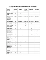
Page 13: ...strainer basket As Required As Required As Required As Required As Required Inspect gaskets X X X Check pump shaft for free rotation X X Check operation of valves X X X Check lubricate clamp on filter tank access port X X Inspect over drain assembly media pack X X X Check pump motor for proper rotation X Check motor voltage current X X X Prime Pump X Check pressure gauge reading top of filter X X ...

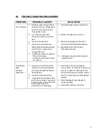
Page 14: ...eplace with proper media sand ConsultyourLAKOSrepresentative 4 Backwash more often at lower differential pressure 5 Add proper sand media to tank s to specified level Consistently High Pressure Differential Excessive contaminant load restricts flow through the filters and prevents sufficient flow for backwashing Insufficient backwash flow Inadequate media sandvolume which may minimize coverage of ...

Page 15: ...s Media Sand Incorrect media sand i e too fine and too 1 Replace media with proper sizedmedia Appears Downstream small Broken damaged or missing lateral 2 Repair or replace laterals of the underdrain Obstruction inthe valve seat Rubber seatingis worn or damaged Actuator Diaphragm damaged Linkage outof adjustment 1 Remove the obstruction Backwash Valve Leaks 2 Replace Valve 3 Replace diaphragm 4 Ad...

Page 16: ...ir movement for cooling Make sure that motor has a fresh source of air for cooling 3 Check voltage with meter System Trips out when running and shuts down Overload setting is too low Supply voltageis incorrect System flow is too high Loose Wire 1 Check overload setting in control panel Overload setting should be just above full load amp value on motor nameplate 2 Check incoming supply voltage with...

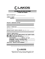
Page 17: ...DS type size etc COOLING TOWER MODEL DOES SYSTEM USE HYDROBOOSTERS IN THE TOWER BASIN Yes No HOW MANY PER CELL Upon start up please record this data MOTOR AMPS MOTOR VOLTAGE PRESSURE TO INLET OFSAND FILTER PRESSURE AT OUTLET OFSAND FILTER BACKWASH DURATION ADDITIONAL OBSERVATIONS REMARKS Please complete this form and send a copy to LAKOS keep a copy for your records 1365 North Clovis Avenue Fresno...

Reviews: